5.8.1 Erection of the Equipment
The erection procedure should be carried out in accordance with the manufacturer’s instructions paying particular attention to the following:
Prior to commencing installation of lifting and pulling machines that have been in storage, a check should be made to ensure that no damage has occurred whilst in store. (See 5.10 IN-SERVICE INSPECTION AND MAINTENANCE)
Lifting and pulling machines may be utilised in many ways. For lifting purposes, they can be used in three different ways as indicated in Figure 5.8.1-1 .
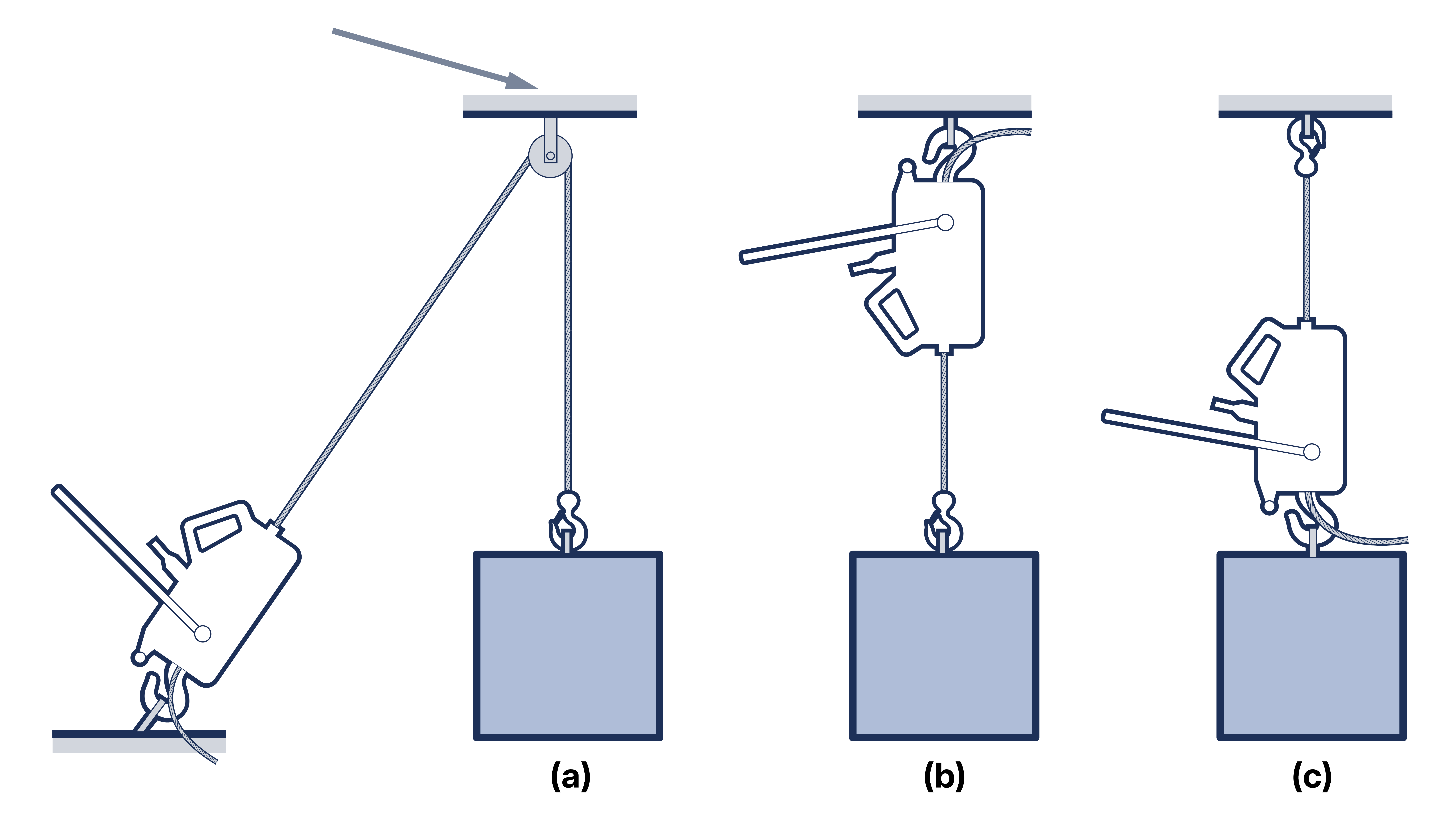
Figure 5.8.1-1 This anchorage must carry 2.08 x load W (see section 1, appendix 1.4)
Figure 5.8.1-1 (a) shows the machine anchored close to the ground with the rope taken over a pulley block fixed directly above the load. Additional pulley blocks may be introduced as required to increase the capacity of the system. This method has the advantage that the operative can stand well away from the load but also has the disadvantage that the load imposed on the overhead anchorage is greater than the load lifted. Figure 5.8.1-1 (b) shows the machine anchored directly to the overhead structure so that the load is lifted towards the machine. One or more pulley blocks can be introduced into the system in a similar manner to that shown in Figure 5.8.1-1 (a). Figure 5.8.1-1 (c) shows the machine anchored directly to the load so that the rope remains static and the machine and load climb the rope.
Lifting and pulling machines are often used in conjunction with sheaves, as shown above. Owing to the special construction of the rope, the ratio of the sheave diameter to the rope diameter must be higher than for an ordinary pulley block system. It is therefore recommended that the ratio of sheave diameter to rope diameter should be not less than 15:1. Therefore pulley blocks should be selected that have been made to standards that provide for such a ratio in their specification.
It is essential to ensure that the structure from which a lifting and pulling machine or its associated pulley blocks and sheaves are suspended is adequate for the load it is intended to carry. For arrangements other than as figure 5.4(a), this load includes the weight of the machine itself together with any associated pulley blocks and sheaves and above hook attachments (e.g. slings, shackles, etc.) and the operating effort plus a 10% additional allowance on the total to take account of the effects of dynamic loading. In the case of arrangements as figure 5.4(a) the suspension will not carry the weight of the machine but will carry an additional load due to the line pull in the rope. (See section 1 appendix 1.4)
The machine should be free to align itself correctly with the rope and the rope itself should not be allowed to snag, catch or rub on any intermediate obstruction.