3.8.1 Erection of the Equipment
The erection procedure should be carried out in accordance with the manufacturer’s instructions paying particular attention to the following:
It is essential to ensure that the structure from which a hoist is suspended is adequate for the load it is intended to carry. This load includes the weight of the hoist itself together with any above hook attachments (i.e. slings, shackles, trolley, etc.) and the operating effort plus a 10% additional allowance on the total to take account of the effects of dynamic loading. Where a travelling trolley of either hook-in or built-in pattern is employed, it is essential that the runway beam, jib arm, etc. is sufficiently level at all loads (up to the maximum for which it is designed) such that the trolley, hoist, etc. will not run away under gravity.
When using a hook suspended hoist, the top hook should be attached to its support in such a manner that the support fits freely into the seat of the hook and does not exert any side thrust upon the point. The top hook should be fitted with a safety catch, but some older hoists made to older standards may not, in which case the hook may be ‘moused’ to prevent displacement. (See Figure 3.8.1-1 ). Where safety catches are not fitted it is recommended that they should be where it is practical to do so.
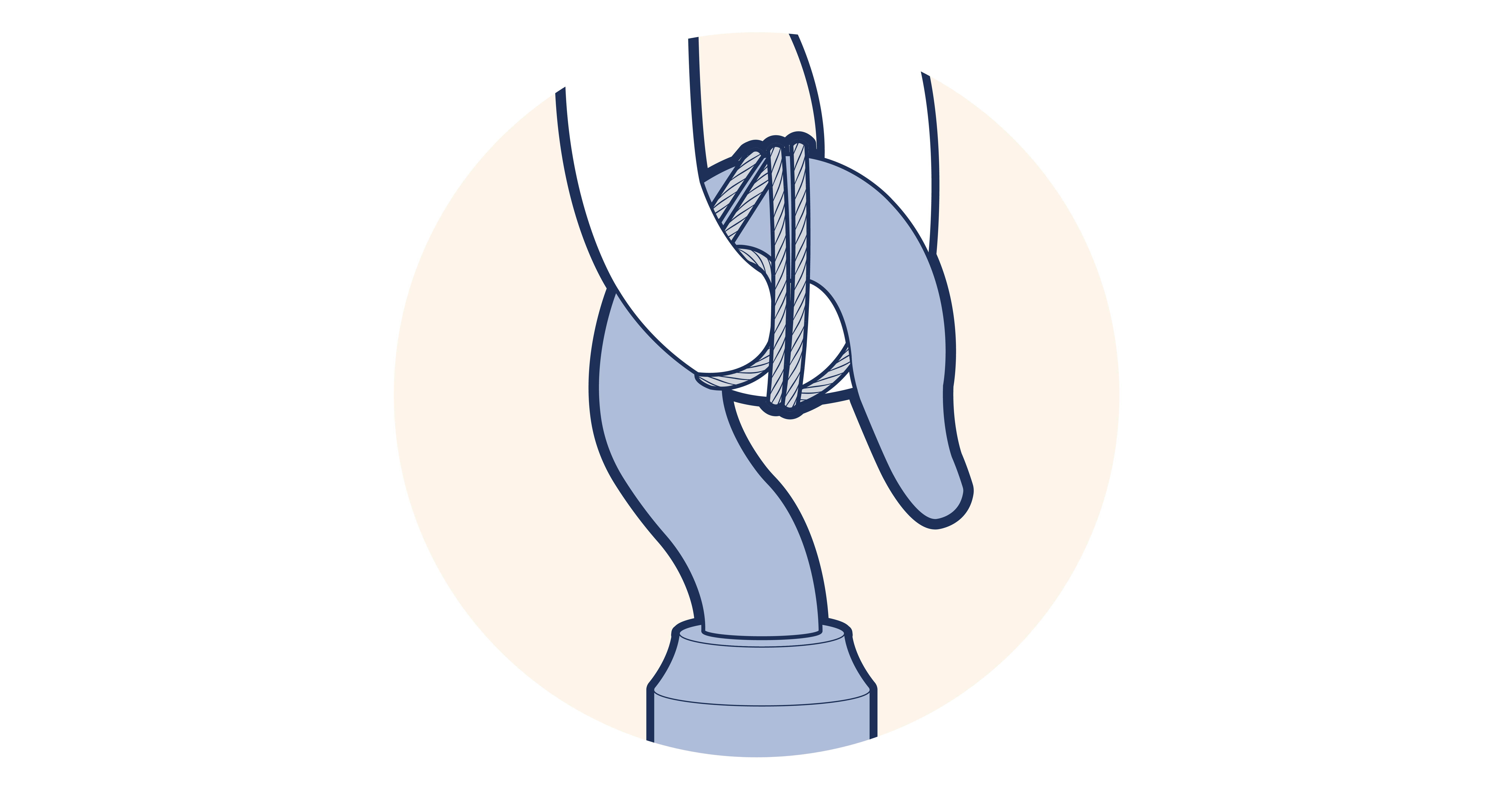
Figure 3.8.1-1 Top hook "moused"
After erection, a check should be made to ensure that the hand and load chains hang freely and are not twisted or knotted. In particular, special care should be taken with multi-fall hoists to ensure that the bottom block has not been turned over between the falls of chain imparting a twist to the load chain. If this has occurred, the bottom block should be carefully turned back until the twist is removed.
The length of the load chain should be checked to ensure that the bottom hook will reach the lowest point required without running the load chain fully out. If the load chain is permitted to run fully out, an undue stress may be placed on the slack end anchorage. The load chain should not be lengthened beyond its designed limit without guidance from the Competent Person in consultation with the manufacturer.
As the length of the load chain increases, so does its weight and this should be taken account of when assessing the SWL. This also applies to the hand chain.
As a load is lifted, chain is transferred from the ‘loaded’ side of the load sheave to the ‘unloaded’ or slack end side. With a long load chain and a light load, the weight of the slack end may counterbalance the load to the extent that once started the load would continue to ascend, thus increasing the weight of chain on the slack end, resulting in an avalanche effect. The fitting of a suitable chain collecting box will prevent this effect.