8.6 INFORMATION WHICH SHOULD BE EXCHANGED BETWEEN THE USER AND THE DESIGNER OR SUPPLIER
As girder trolleys are frequently used for miscellaneous lifting applications, precise details of the load to be carried are not always available. In these circumstances, only a general specification can be given, and this should include the following:
Type of trolley required.
Details of the runway beam section to which the trolley is to be fitted. These details must be sufficient to fully identify the particular section or in the case of a fabricated section, the various elements from which it is manufactured. In addition, details of fixing bolts, clips, splices, etc. are required to ensure that they will not foul the load bar, trolley wheels or anti-tilt device where fitted. (See Figure 8.6-1 )
Details of the supporting structure of the runway including clearance dimensions to other structures or items of plant to ensure that there will be no external obstruction to the operation of the trolley and lifting appliance.
The total maximum weight to be lifted.
The type (including whether manual or power operated) and class of use of lifting appliance to be used with the trolley.
Details of the load bar or suspension point of the trolley and the attachment point of the lifting appliance(s) to be fitted.
If a geared trolley is specified, then the suspension and operating levels are required so that the length of hand chain may be determined.
The minimum radius curve, if any, of the runway.
Environmental considerations such as extremes of temperature or corrosive atmospheres.
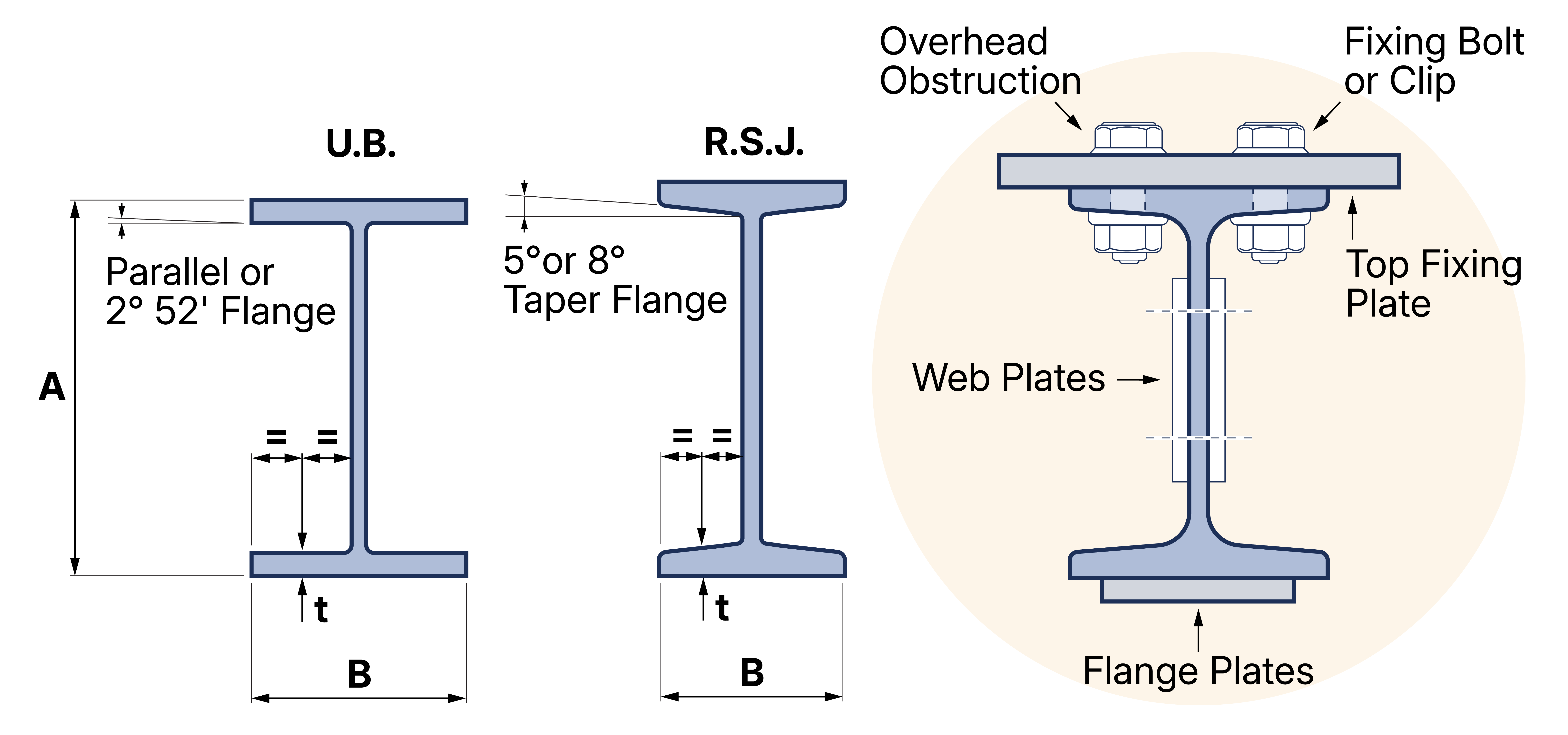
Figure 8.6-1 Types of beam
Indicate whether: parallel flange, tapered flange, fabricated beam, etc. Also indicate end stops, joint plates, etc.
As an example, a trolley may be described as follows:
250kg rated capacity:
Gear operated:
Four plain bearing wheels:
Rigid trolley:
Flange width 150mm parallel flange:
Suitable for use with hook suspended hand chain hoist.