7.8.1 Erection of Equipment
The erection procedure should be carried out in accordance with the manufacturer’s instructions paying particular attention to the following:
Before installation, thoroughly check winches and associated equipment from storage to ensure no damage or deterioration has occurred during storage.
Ensure that the foundation, wall, or structure used to mount or suspend the winch is compatible with the fixings and can handle the intended load. Timber bearers are unsuitable and should not be used, indeed they were prohibited by some of the older legislation. If pulley blocks are to form part of the rigging assembly, their suspensions must be adequate for all of the loads that will be imposed. When pulley blocks are used, the load imposed on the supporting structure, connections and fixings is increased by virtue of the hoisting effort and the effects of friction. (See 7.5.6 Rigging Arrangement and Table 1) The imposed load also includes the weight of the pulley blocks together with any attachments, (e.g. clamps, shackles, slings, etc.) plus an additional allowance for dynamic loading. In the case of manually, operated equipment a dynamic allowance of 10% and in the case of powered equipment a dynamic allowance of 25% should be made.
The winch drum must be positioned so that it is square to the line of pull. If the wire rope runs over a lead block or diverter pulley, an angled pull will result as the rope feeds on and off the drum across its width. This is known as the angle of fleet. It is the recommendation of some winch standards that the first lead block around which the rope passes should be positioned centrally between the drum flanges and not be less than 6 times the length of the drum away from the drum axis. This gives a maximum fleet angle of a little over 4.5º. However, wire rope standards recommend that for optimum rope life the maximum angle of fleet for grooved drums should not exceed 2.5º and for plain drums it should not exceed 1.5º. In practical terms, this means that the distance from the drum axis to the first lead block should be at least 12 for grooved drums and 19 for plain drums. (See Figure 7.8.1-1 )
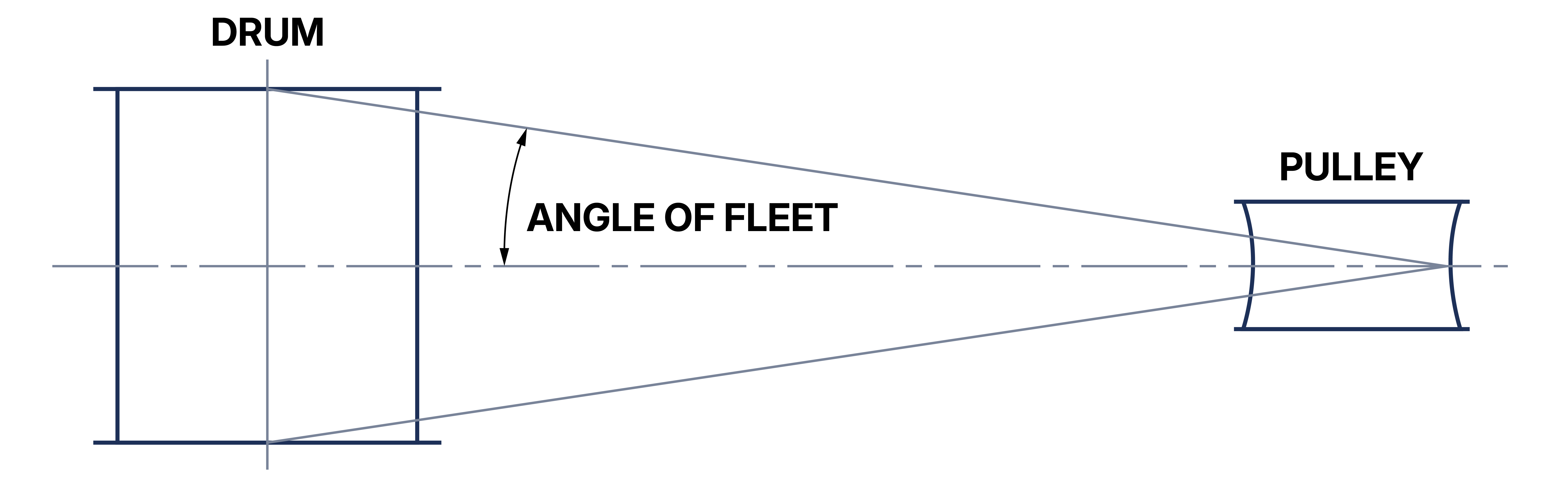
Figure 7.8.1-1
Steps must be taken to ensure that the wire rope is strong enough for the application and long enough to leave at least the minimum number of dead turns on the drum when it is in its fully extended position. The wire rope must not over fill the drum and the width between the outer layer of rope and the outer edge of the flange should not be less than 2 times the rope diameter. The rope must be properly anchored to the drum in such a way that the anchorage does not obstruct the free coiling of the rope onto the drum.
It must be remembered that running ropes and pulleys can be a source of danger, even if they are slow moving. The rigging arrangement should, as far as possible, ensure that these items are installed in such a way that any danger is minimized, either by virtue of their position or by guarding.
After erection, a check should be made to ensure that the wire rope runs and hangs freely and is not twisted or obstructed. Care should be taken when using multi-fall blocks to ensure the bottom block has not been turned over between the rope falls imparting a twist to the rope. Exercise great care when removing such a twist as permanent damage may be caused to the rope by careless handling.