14.5.2 Method of Use
The factors to be considered fall into three main groups:
Those dealing with the way the sling is attached to the load.
Those dealing with the geometry of the sling, i.e. the angle of the legs to the vertical and the disposition of the legs in plan.
Those dealing with the number of legs in use.
The amount of load that will be carried by an individual leg will depend on the angle between each of the legs and the vertical, the disposition of the legs in plan view and the total load being lifted.
The reduced ratings for slings when used in choke hitch take account of higher stresses at the point where the choking hook or link bears upon the chain.
The following examples are based on slings which have been rated and marked to the uniform load method. The SWL marked on uniform load rated multi-leg chain slings is for a range of angles from 0- 45° to the vertical (0- 90° included angle) and, if requested by the purchaser, an additional mark showing the reduced SWL for angles of 45°-60° (90°-120°). This assumes that the legs are equally disposed about the vertical and symmetrically disposed in plan. (See section 1 1.A5.5.2 Rating Assumptions) If a tilt occurs due to the centre of gravity being misjudged or if unequal angles to the vertical are formed, then the leg with the smaller angle to the vertical will have a larger share of the load imposed upon it.
14.5.2.1 Single leg sling in straight lift
When a single leg sling is used for a straight lift, the maximum load to be lifted must not exceed the SWL marked on the sling. (See Figure 14.5.2.2-1 a)
14.5.2.2 Single leg sling in choke hitch
When a single leg sling is used in a choke hitch, the maximum load to be lifted must not exceed 0.8 x the SWL marked on the sling. (See Figure 14.5.2.2-1 b)
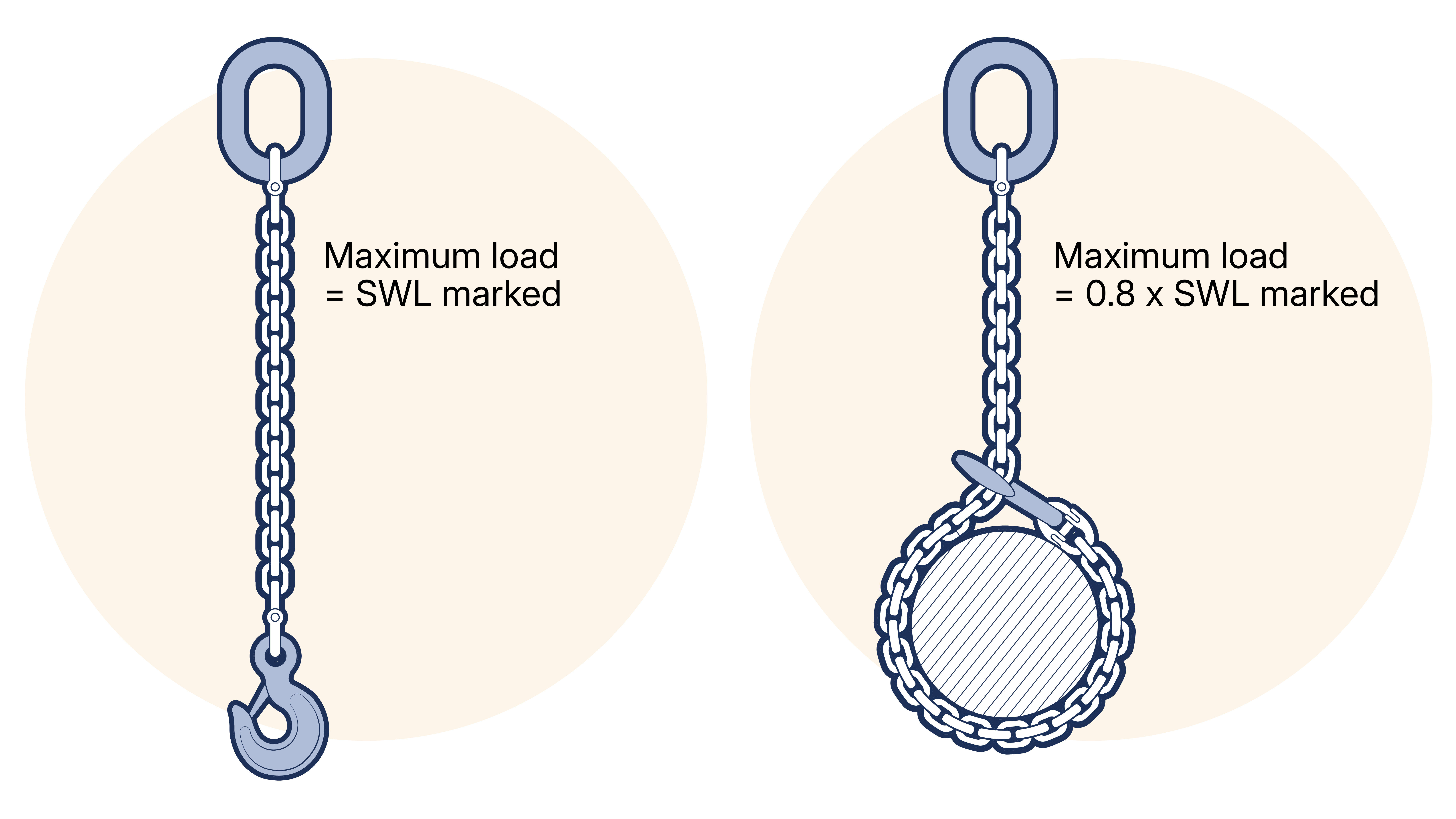
Figure 14.5.2.2-1 A. Single leg sling in straight lift. B. Single leg sling in choke hitch.
14.5.2.3 Single leg sling in basket hitch
When a single leg sling is used in basket hitch by hooking back to the master link, with the parts of chain inclined at angles between 0-45° to the vertical (0-90° between the parts of chain), the maximum load to be lifted must not exceed the SWL marked on the sling as in this arrangement the full load is taken by the master link. (See Figure 14.5.2.3-1 a)
When a single leg sling has master links at each end and is used in basket hitch with both links on the hook and with the parts of the chain inclined at angles between 0-45° to the vertical (disposed at an included angle of 0-90°), the maximum load to be lifted must not exceed 1.4 x the SWL marked on the sling. In this arrangement, the load is shared between the master links. (See Figure 14.5.2.3-1 b)
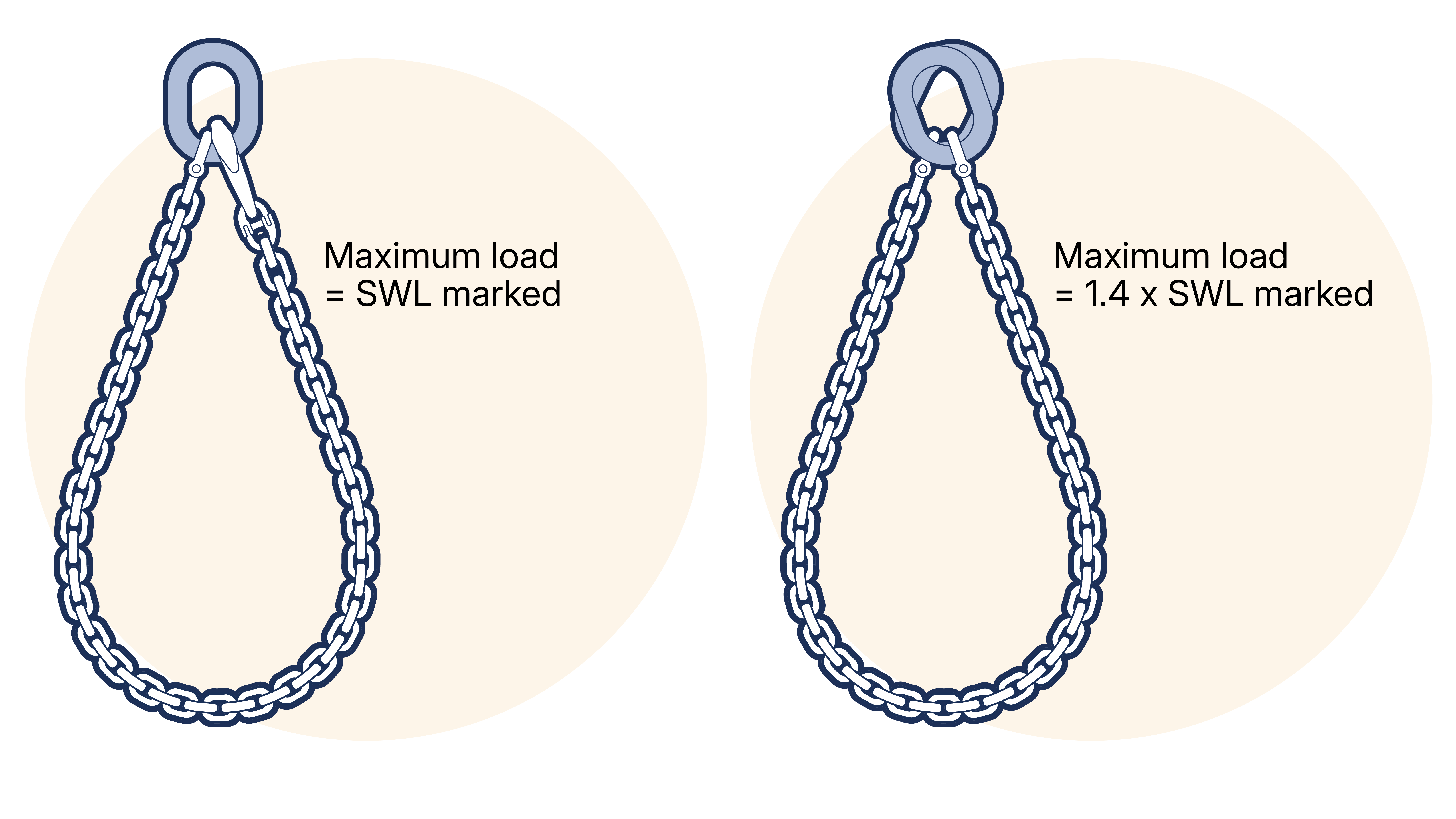
Figure 14.5.2.3-1 A. Single leg sling in basket hitch hooked back to master link. B. Single leg sling in basket hitch with both master links to hook.
14.5.2.4 Two leg sling in straight lift
When a two leg sling is used for a straight lift, the maximum load to be lifted must not exceed the SWL marked on the sling for the appropriate range of angles. (See Figure 14.5.2.4-1 )
When two single leg slings, of the same length and SWL, are used for a straight lift, the maximum load to be lifted must not exceed 1.4 x the SWL marked on a single sling when the legs are inclined at angles between 0-45° to the vertical (included angle between the legs is in the range 0-90°). The use of two single slings at angles to the vertical of greater than 45° (included angle greater than 90°) is not recommended. (See Figure 14.5.2.4-2 )
Figure 14.5.2.4-1 Two leg sling in straight lift
Figure 14.5.2.4-2 Two simple leg slings in straight lift
14.5.2.5 Two leg sling in choke hitch
When a two leg sling is used in a choke hitch, the maximum load to be lifted must not exceed 0.8 x the SWL marked on the sling for the appropriate range of angles. (See Figure 14.5.2.5-1 a)
When two single leg slings, of the same length and SWL, are used in a choke hitch, the maximum load to be lifted must not exceed 0.8 x the maximum load rating obtained for straight lift as in 14.5.2.4 Two leg sling in straight lift when the legs are inclined at angles between 0-45° to the vertical (0-90° included angle). The use of two single slings at angles to the vertical of greater than 45° (included angle greater than 90°) is not recommended. (See Figure 14.5.2.5-1 b)
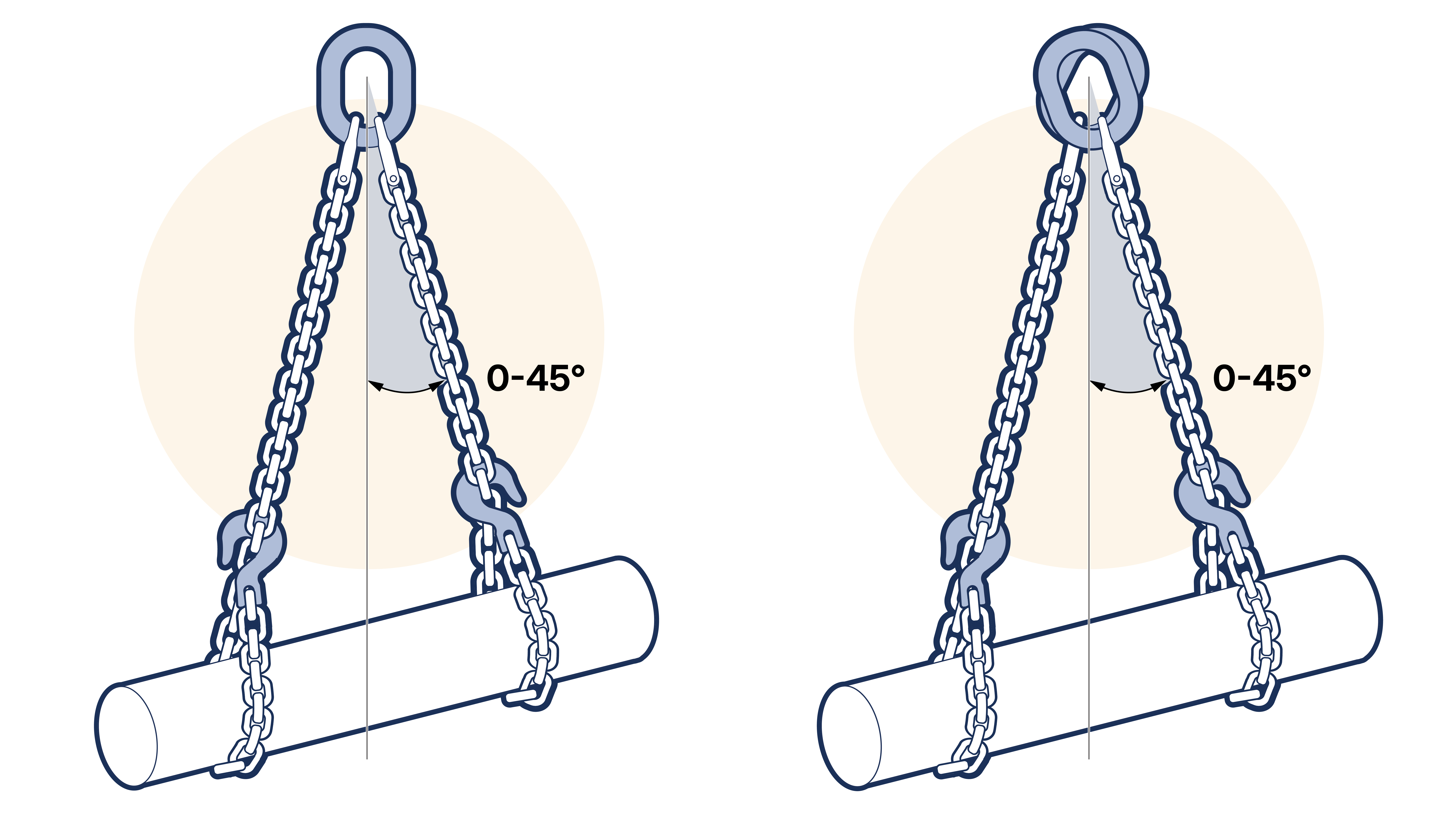
Figure 14.5.2.5-1
14.5.2.6 Two leg sling in basket hitch
When a two leg sling is used in basket hitch the maximum load to be lifted must not exceed the SWL marked on the sling for the appropriate range of angles. In this case the angle between the vertical or included angle formed between any two parts of chain must not be in excess of that permitted by the appropriate range. (See Figure 14.5.2.6-1 a)
When two single leg slings, of the same length and SWL, are used in basket hitch, the maximum load to be lifted must not exceed 1.4 x the SWL marked on a single sling when the legs are inclined at angles between 0-45° to the vertical (0-90° included angle) The use of two single slings at angles to the vertical of greater than 45° (included angle greater than 90° is not recommended. (See Figure 14.5.2.6-1 b)
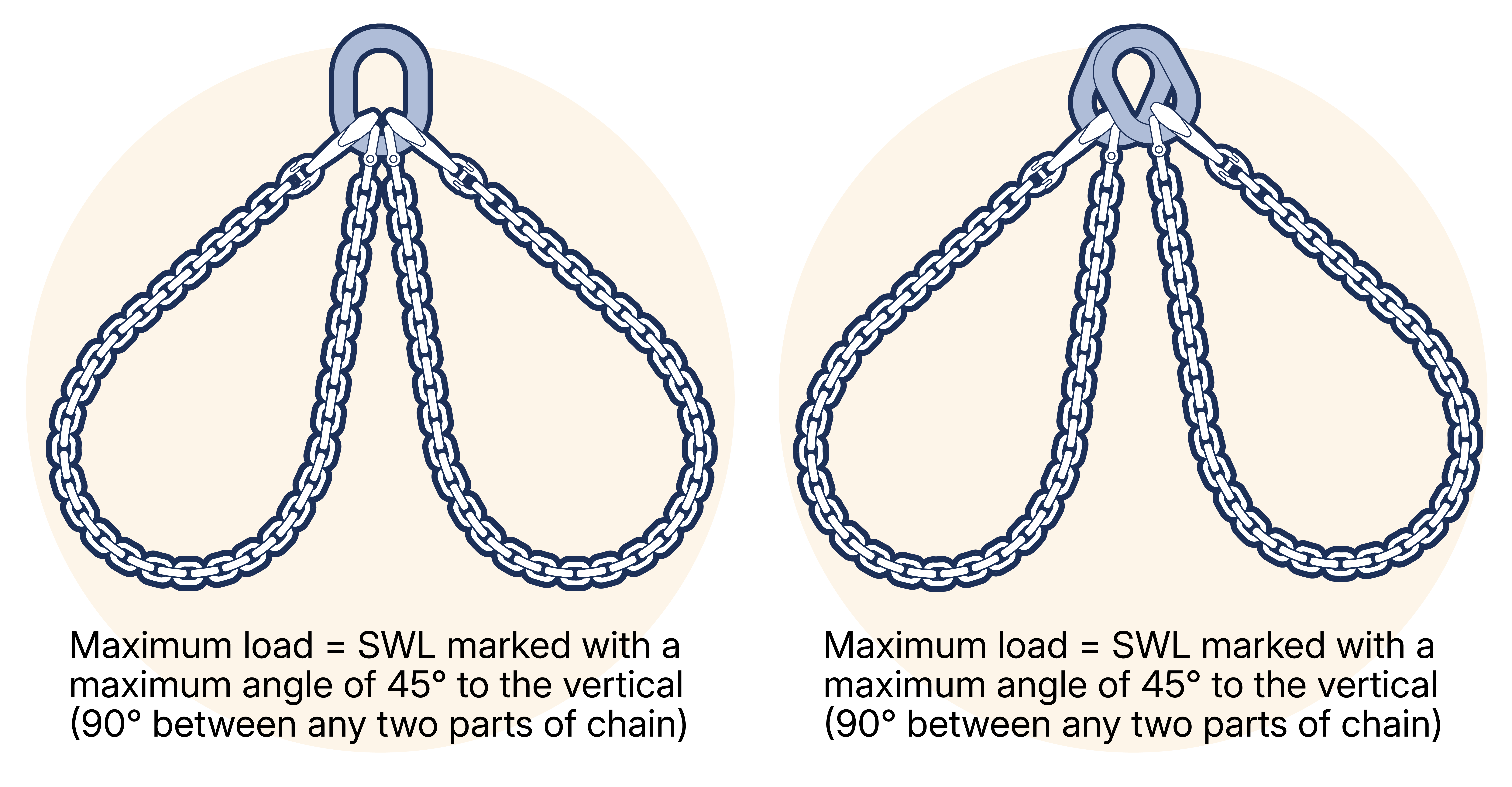
Figure 14.5.2.6-1 A. Two leg sling in basket hitch. B. Two single leg slings i basket hitch.
To prevent the hook of the lifting appliance becoming overcrowded, LEEA recommends that the upper ends of the sling legs are connected by a shackle of adequate strength.
14.5.2.7 Three leg sling in straight lift
When a three leg sling is used for a straight lift, the maximum load to be lifted must not exceed the SWL marked on the sling for the appropriate range of angles. Where this is given for the included angle it should be taken as twice the angle between the sling leg and the vertical i.e. 2 x β. (See Figure 14.5.2.7-1 )
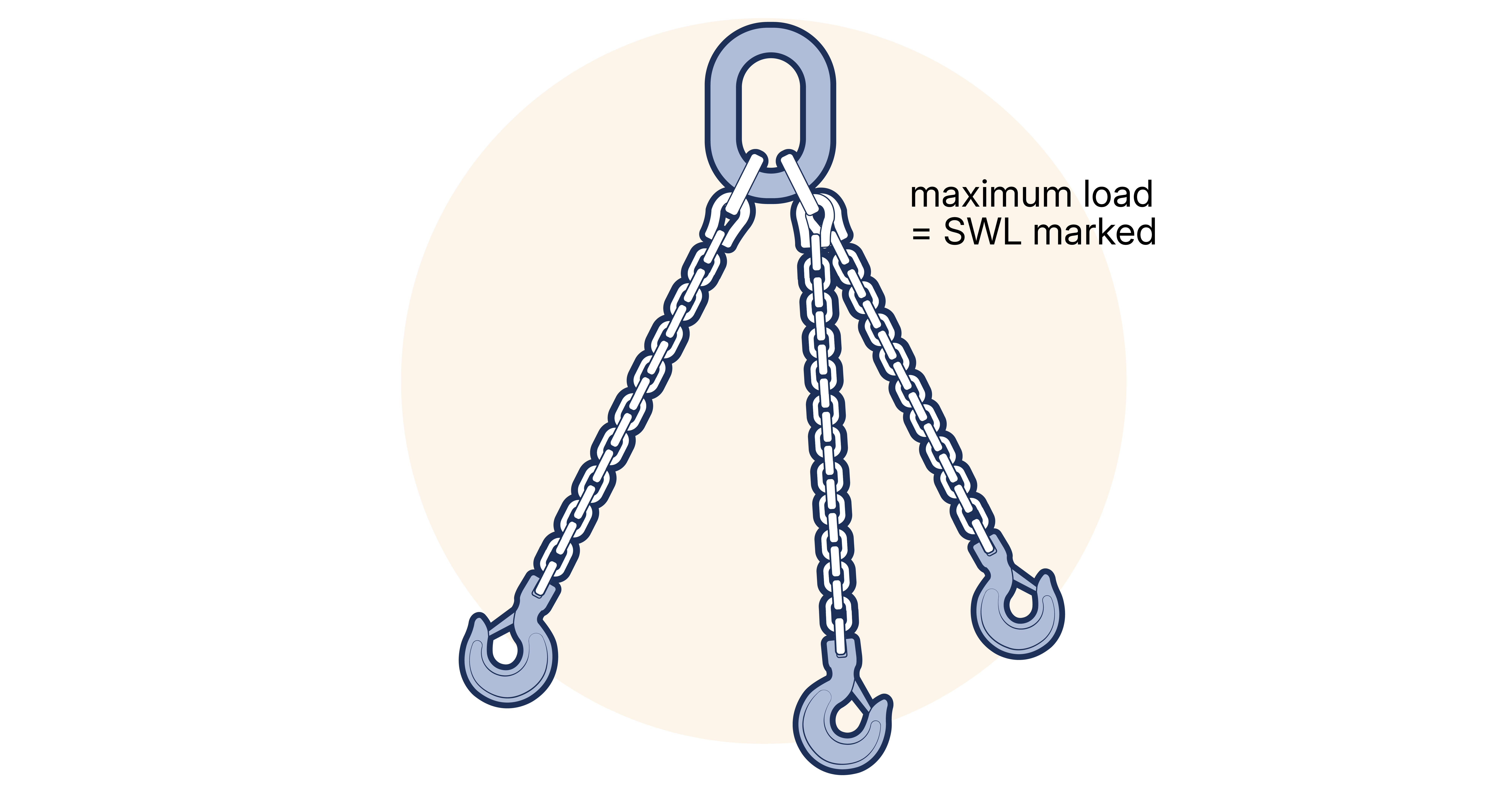
Figure 14.5.2.7-1
14.5.2.8 Three leg sling in choke hitch
When a three leg sling is used in a choke hitch, the maximum load to be lifted must not exceed 0.8 x the SWL marked on the sling for the appropriate range of included angles. The included angle should be taken as twice the angle between the sling leg and the vertical i.e. 2 x β.
14.5.2.9 Three leg sling in basket hitch
When a three leg sling is used in a basket hitch, the maximum load to be lifted must not exceed the SWL marked on the sling for the appropriate range of included angles. In this case, the included angle, i.e. 2β, between any two parts of chain must not be in excess of that permitted by the appropriate range.
14.5.2.10 Four leg sling in straight lift
When a four leg sling is used for a straight lift, the maximum load to be lifted must not exceed the SWL marked on the sling for the appropriate range of angles. The included angle, i.e. 2 x β, should be measured between diagonally opposite legs. (See Figure 14.5.2.13-1 a)
14.5.2.11 Four leg sling in choke hitch
When a four leg sling is used in a choke hitch, the maximum load to be lifted must not exceed 0.8 x the SWL marked on the sling for the appropriate range of angles. The included angle, i.e. 2 x β, should be measured between diagonally opposite legs.
14.5.2.12 Four leg sling in basket hitch
When a four leg sling is used in basket hitch, the maximum load to be lifted must not exceed the SWL marked on the sling for the appropriate range of angles. In this case, the included angle, i.e. 2 x β, between any two parts of chain must not be in excess of that permitted by the appropriate range.
14.5.2.13 Double basket sling
When a double basket sling is being used, the maximum load to be lifted for the appropriate range of angles must not exceed the SWL marked on the sling. The included angles should be measured between any diagonally opposite parts of chain. (See Figure 14.5.2.13-1 b)
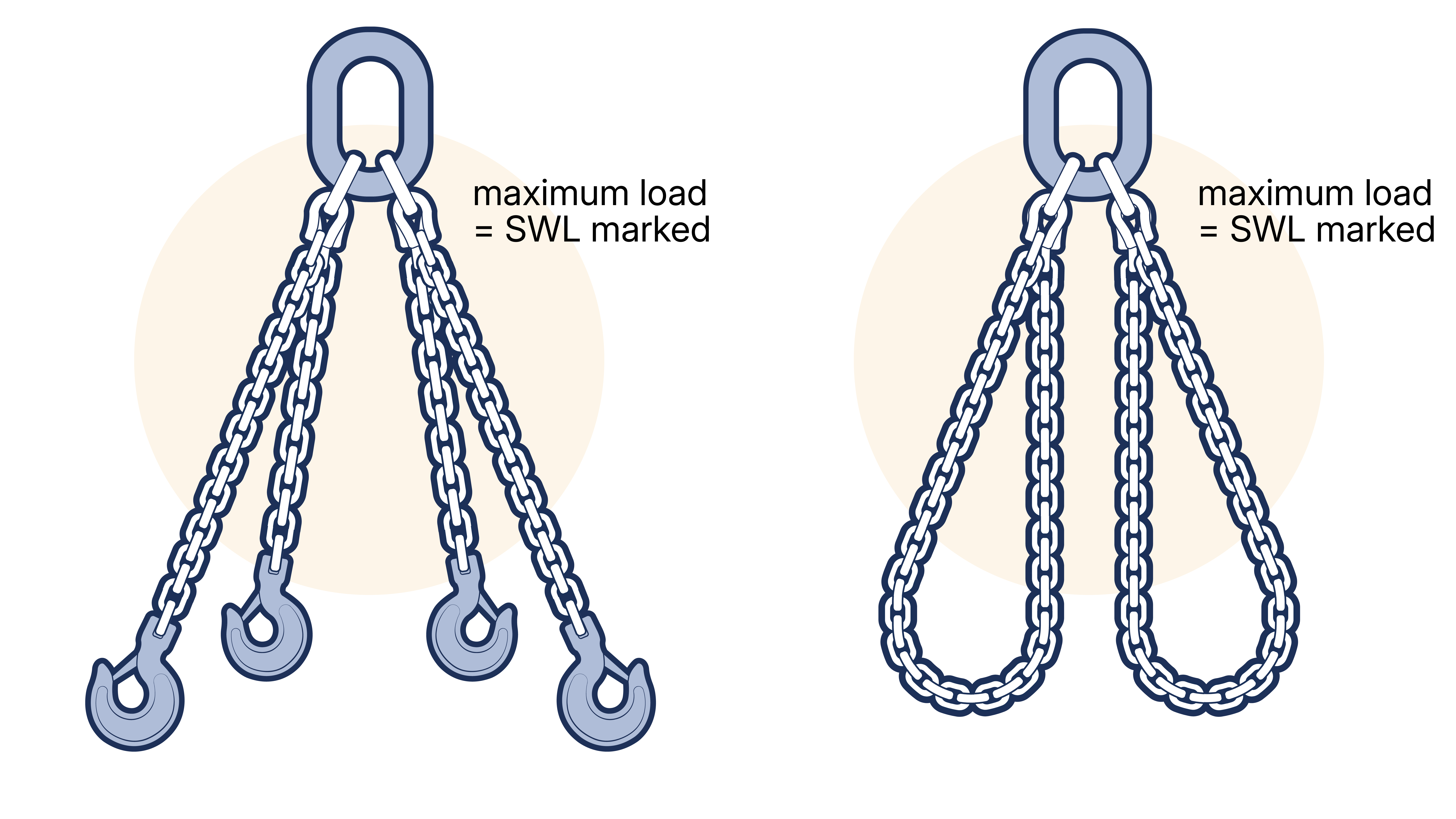
Figure 14.5.2.13-1
14.5.2.14 Endless sling
An endless sling should be used only in the configuration shown in figure Figure 14.5.2.14-1 . The maximum load to be lifted must not exceed the SWL marked on the sling.
In the case of a sling with a mechanical joining device, the device should be positioned in one of the straight sections, away from the load, bight or appliance hook.
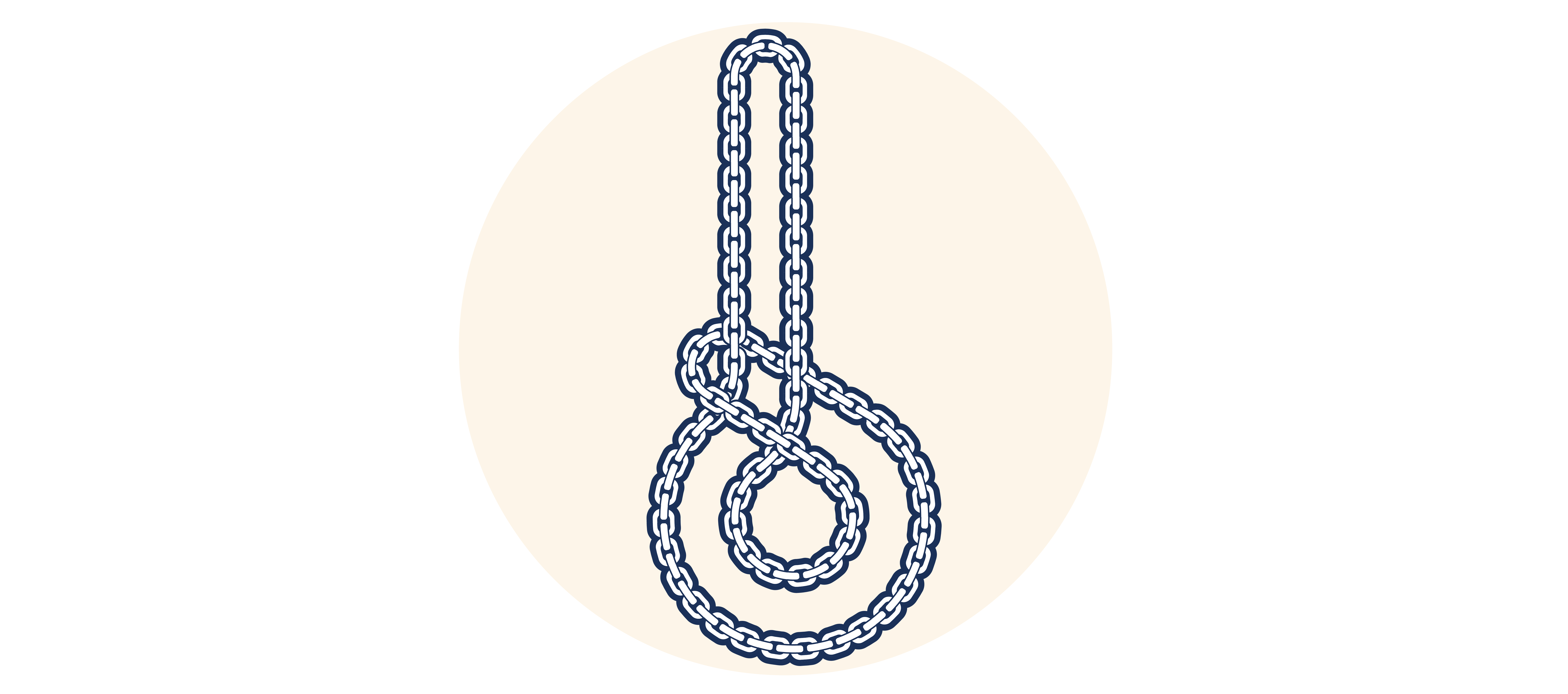
Figure 14.5.2.14-1 Endless sling
14.5.2.15 Adjustable slings
Most manufacturers can incorporate shortening devices into all sling assemblies rendering them adjustable. (See section 14.4 TYPES OF CHAIN SLING) Shortening clutches are the preferred devices for adjusting leg length as they maintain the correct ‘in line loading’ of the chain so that the rating is not affected. The use of hooks that lock onto a link of the chain, commonly known as grab hooks, is not recommended for this purpose as they involve a transverse or oblique loading on the chain. If a manufacturer provides grab hooks for shortening purposes, their recommendations on de-rating must be sought and followed. Another, more appropriate, type of grab hook that is sometimes used is the cradle type and again if using these the manufacturer’s instructions must be strictly adhered to.
Shortening devices in multi-leg slings will adjust the leg length, but care must be taken to ensure that no one leg is overloaded as a result. Bear in mind that if the legs are not equally disposed about the vertical, the leg making the smaller angle to the vertical will carry a larger share of the load. Such shortening devices MUST be used correctly with the load bearing chain always leading out from the bottom of the device. (See Figure 14.5.2.15-1 for illustrations of correct and incorrect usage)
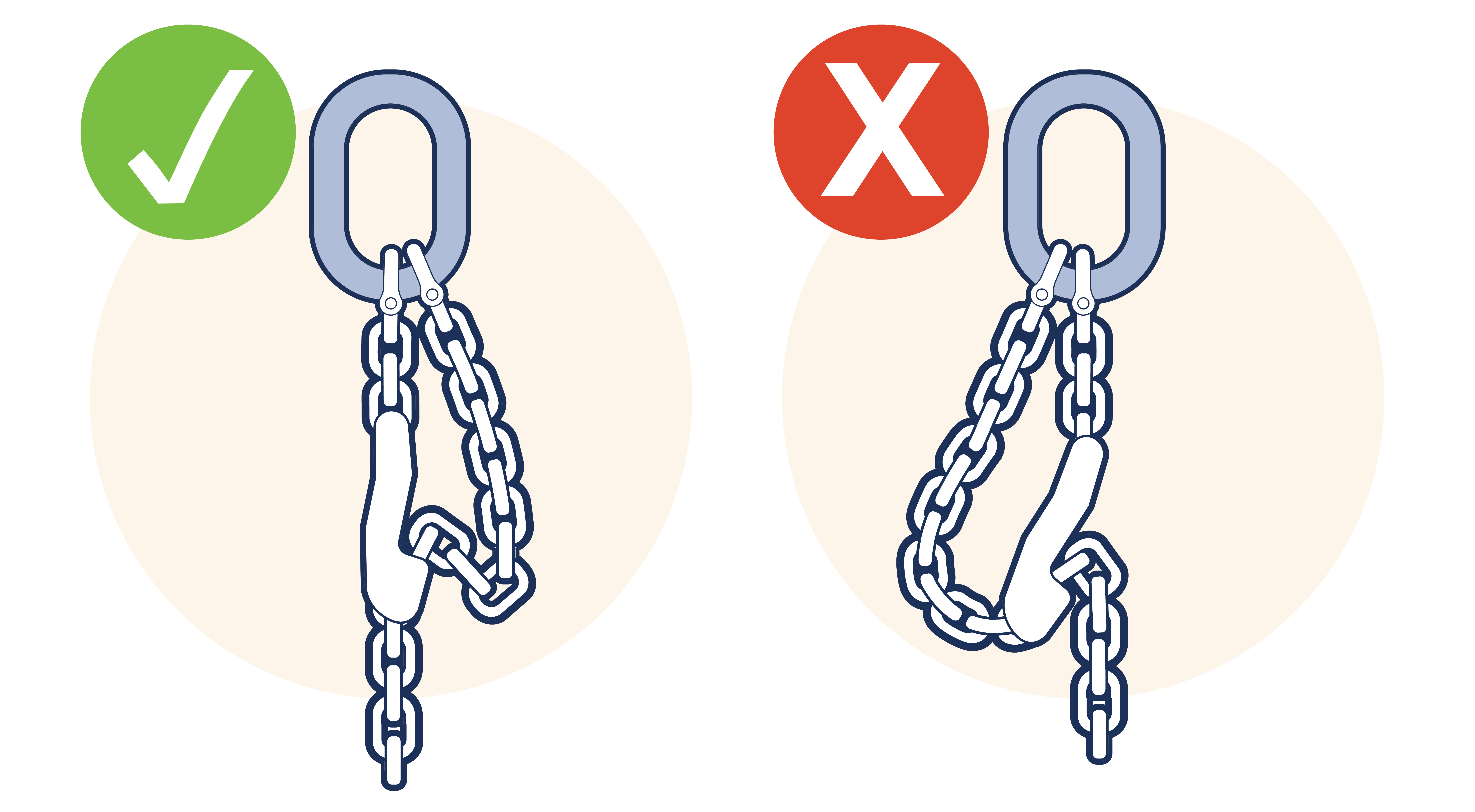
Figure 14.5.2.15-1 Use of shortening clutches in adjustable slings. Note that the loaded end of the chain must come out of the bottom of the clutch.
14.5.2.16 The use of multi-leg slings with less than the total number of legs in use
Occasionally, it may be necessary to use a multi-leg sling with less than the total number of legs employed in the lift. With care this may be done safely.
The reduced SWL for multi-leg slings with less than the full number of legs in use may be calculated exactly. This however requires several factors to be taken into account and the calculation may become complex. A simple method requiring the minimum of calculation has been devised which can be safely applied to any sling.
Care must be taken to ensure the rules of rating slings for different slinging methods are also applied to any multi-leg sling used this way. That is to say, for example, a four leg sling with only two legs in use must be treated as a two leg sling, the reduced SWL being subjected to any further reduction factors applicable to two leg slings due to the method of use.
To calculate the maximum load that can be lifted by any combination of legs, simply multiply the marked SWL by the number of legs in use expressed as a fraction of the total number of legs in the sling. For example, a two leg sling with only one leg in use can lift = 1/2 x SWL marked on sling.
Table 1 gives the simplified reduction factors which should be applied to the marked SWLs of multileg slings when less than the full number of legs are in use.
Total number of legs in sling | Number of legs in use | ||
|---|---|---|---|
1 | 2 | 3 | |
2 | ½ | 1 | - |
3 | ⅓ | ⅔ | 1 |
4 | ¼ | ½ | ¾ |
The reduced SWL calculated by this method will ensure that the sling is never overloaded. The adoption of the above method means that in some cases the sling will be under utilised, although this is unlikely to hinder the user unduly. If, however, the maximum utilisation is required, reference should be made to a Competent Person who understands the factors involved and who can perform the necessary calculations.