1.A5.5 SAFE USE OF SLINGS
The basic objective of good slinging practice must be to ensure that the load is safe and, when slung, is as secure in the air as it was on the ground.
1.A5.5.1 Basic Principles
The sling and its method of use should be suitable for the load.
The method of attachment of the sling to the load and the sling to the lifting appliance should be secure.
No part of the sling should be overloaded either by the weight of the load or by the method of slinging.
The slinging method should ensure that the load is secure and that the load will not fall from the sling.
The load should be balanced and stable and should not violently change its attitude when lifted.
The load must not be damaged by, or cause damage to, the sling.
Advice on load estimation, load security, centre of gravity, balance and stability is given in appendices 1.A2 APPENDIX 2 - LOAD ESTIMATION - WEIGHT AND CENTRE OF GRAVITY and 1.A3 APPENDIX 3 - LOAD SECURITY - BALANCE AND STABILITY of this section of the code.
1.A5.5.2 Rating Assumptions
The two methods of rating multi-leg slings have been described in section 1.A5.4.3 Methods of Rating Lifting Slings. Both of these methods do however assume certain conditions of use which are imposed to ensure that no part of the sling can become overloaded. It is important to understand that although the weight to be lifted may be within the maximum lifting capacity of the sling, lifting in the wrong way can place an excess of load onto one part of the sling. Although deviations from the assumed conditions have the same effect whichever method of rating is used, it varies in degree and it is with the multipurpose slings where the designer has least information about possible applications and where the onus to make allowance for the actual method of slinging employed therefore falls on the user.
The first of the assumptions is that the sling legs are symmetrically disposed in plan, i.e. for three leg slings, all included angles between the legs in plan are equal; for four leg slings, opposite included angles between adjacent legs, in plan, are equal.
The effect of tilt of the load during the lifting operation is also significant and becomes increasingly more so as the included angle between the legs decreases. As tilt increases, the loading in the leg on the ‘downhill’ side (i.e. the leg with the smaller angle to the vertical) increases.
A further assumption, particularly applicable to multi-leg slings but also applicable to single leg and endless slings where more than one are used, is that all legs are of identical materials and load bearing capacity.
Assumptions are also made with regard to the method of attachment. Single leg and multi-leg slings are rated for use with the leg or legs in a ‘straight pull’, i.e. the legs are not bent around the load, choked, back hooked or otherwise prevented from taking up a straight line under load.
There may be some variation from these assumptions, and this may in fact be desirable offering a more secure way of attaching to certain loads. The options, together with the appropriate changes to the slinging factors to be applied to the standard ratings, are given in Table 1.
MODE FACTORS Maximum load to be lifted = mode factor x SWL marked on the sling Key: NP = non preferred, NA = not applicable | ||||||||
|---|---|---|---|---|---|---|---|---|
1 | 2 | 3 | 4 | 5 | 6 | 7 | 8 | 9 |
Material | Single leg in line 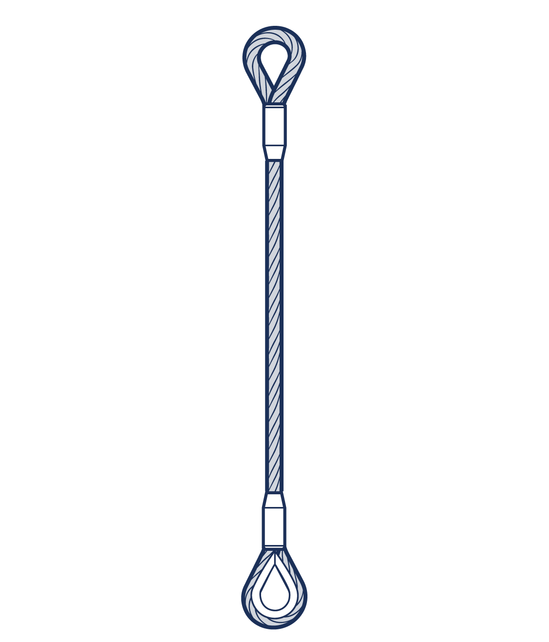 Figure 1.A5.5.2-1 | Single leg choked 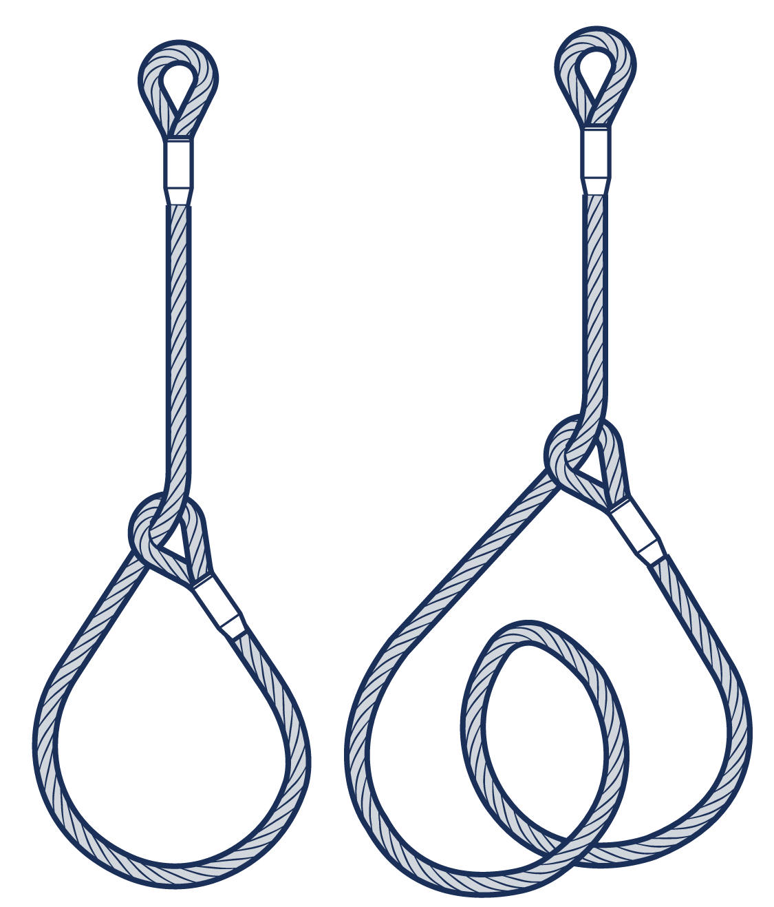 Figure 1.A5.5.2-2 | Single leg basket 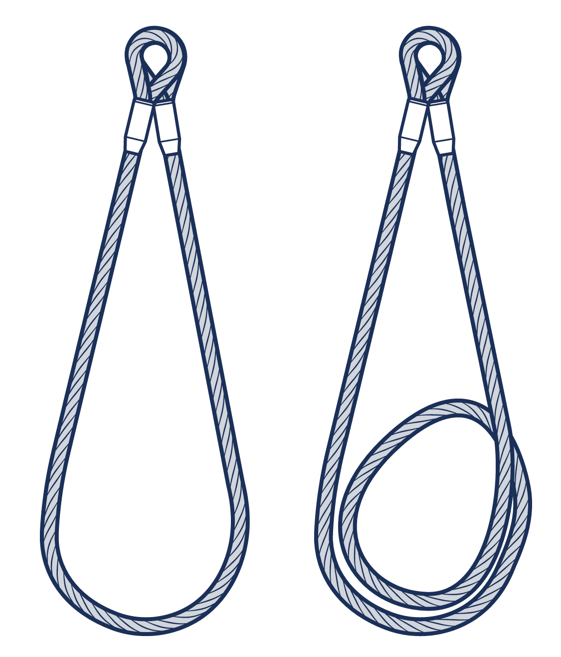 Figure 1.A5.5.2-3 | Single leg back hooked 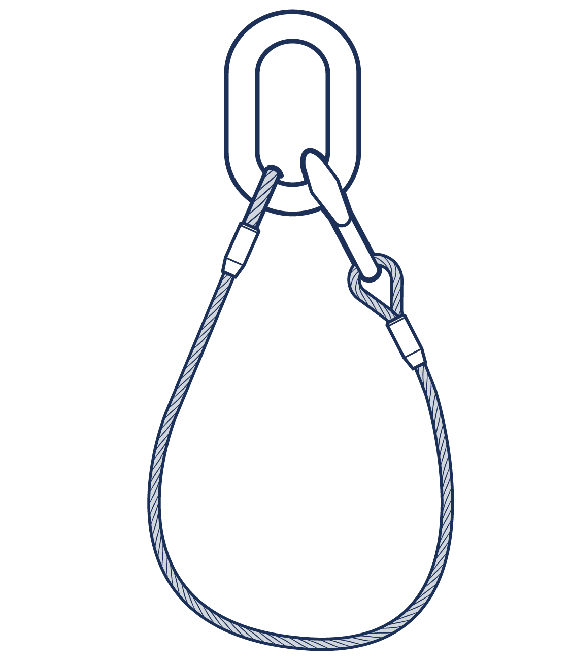 Figure 1.A5.5.2-4 | Single leg halshed 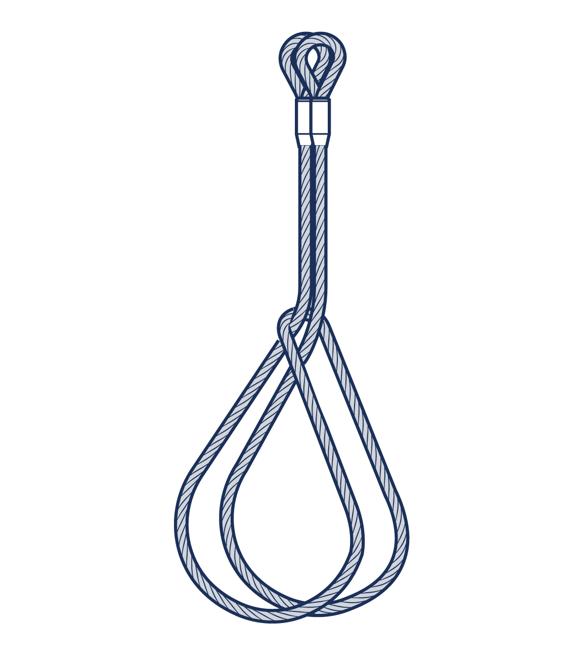 Figure 1.A5.5.2-5 | Endless in line 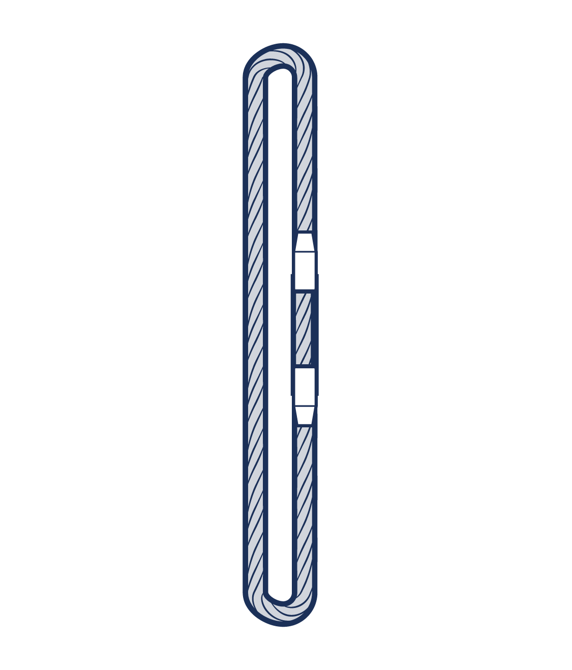 Figure 1.A5.5.2-6 | Endless Choked 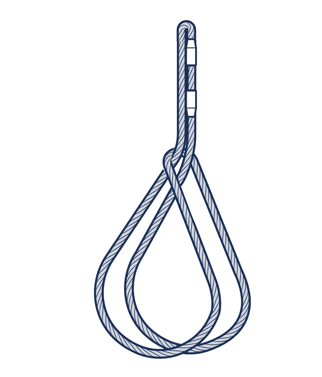 Figure 1.A5.5.2-7 | Endless basket 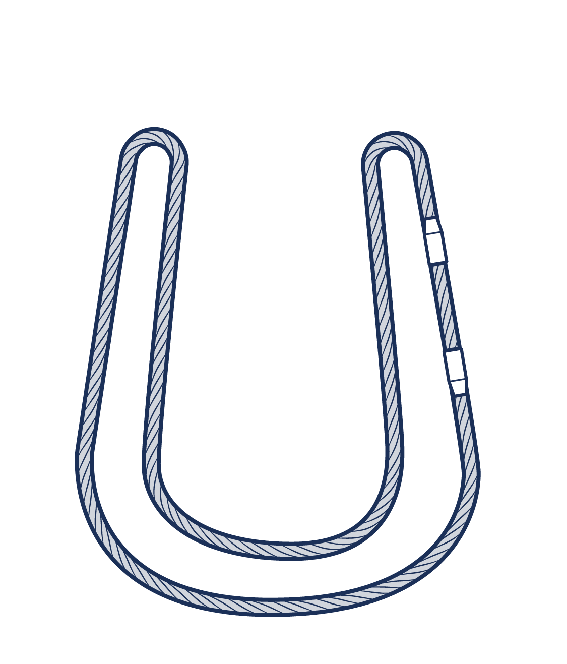 Figure 1.A5.5.2-8 |
Chain | 1 | 0.8 | 1.4 | 1 | NP | NP | 1 | NP |
Wire rope | 1 | 0.8 | 1.4 | 1 | 1.6 | NP | 1 | 1.4 |
Webbing | 1 | 0.8 | 1.4 | NA | NP | 1 | 0.8 | 1.4 |
Fibre rope | 1 | 0.8 | 1.4 | 1 | 1.6 | 1 | 0.8 | 1.4 |
Roundsling | NA | NA | NA | NA | NA | 1 | 0.8 | 1.4 |
Endless slings have fewer variations of use, but it should be remembered that the slinging factor for endless chain and wire rope slings assumes choke hitch, whereas the standard rating for textile slings assumes a straight pull.
In all cases, it is also assumed that, at the points of attachment to both the lifting appliance and the load, the radii around which the sling passes are large enough to avoid damage to the sling. In the case of chain and wire rope endless slings, the rating takes account of the chain and wire rope being bent around itself on the bight.
The mode factors in Table 1are common factors applicable to most slings. However some manufacturers may deviate from these and therefore it is advised that the manufacturer’s instructions take precedence.
1.A5.5.3 Sling Geometry
1.A5.5.3.1 General
If the slinging geometry does not comply with the assumptions given in section 1.A5.5.2 Rating Assumptions, then the load will not usually be evenly distributed amongst the legs. The amount of load that will be imposed on an individual leg depends upon the following:
The angle between each of the legs and the vertical.
The number of legs in the sling, or in use.
The distribution of the legs in plan view.
The total load being lifted.
The relationship between these factors is a complex one especially for three and four leg slings. What happens as these factors vary can be identified in general terms although to quantify the effect requires calculation.
1.A5.5.3.2 Two leg slings
For a two leg sling, if each leg has the same angle to the vertical, then the load will be shared equally between them. If, however, one leg has a smaller angle to the vertical than the other, that leg will have a greater share of the load imposed upon it. This will result in the load tilting. The sling may also not be symmetrical due to the position of the attachment points
The effect of unequal angles increases as the difference between the angles increases. Additionally, the effect is more significant as the angle between the legs decreases although with a uniform load rated sling this is offset to a certain extent because at such an angle there is a degree of redundancy available. This redundancy is however insufficient to fully counter the effect.
As a guide, at an included angle of 30° a difference of angles to the vertical of 12°, i.e. equal to 6° of tilt, will load the downhill leg, i.e. the leg with the smaller angle to the vertical, to its maximum rating if the sling is lifting to its maximum rated capacity. This effect becomes even more significant for three and four leg slings.
1.A5.5.3.3 Three and four leg slings
For three and four leg slings, a difference between the angle each leg has to the vertical has a similar effect to a different degree, but in addition the problem becomes three-dimensional in that the distribution of the legs, when viewed in plan, also affects the share of the load imposed on each leg. The sling geometry of three and four leg slings is as follows:
Three leg slings: With a three leg sling it is assumed that, viewed in plan, the legs are at 120° to each other. If two of the legs are closer than that, the third leg will receive a greater share of the load. Ultimately, if two of the legs are side by side, i.e. at zero angle to each other then they will receive only half the load between them leaving the third leg to take the other half on its own and thus be overloaded.
Four leg slings: With a four leg sling, it is assumed that viewed in plan, the legs are symmetrically disposed, the lower attachment points making the corners of a rectangle. Ideally, the nearer the rectangle is to a square the better, but this is by no means essential. However, as for the two leg slings, the smaller the included angle between the legs the greater the effect of unequal angles. On a four leg sling, the unequal effect can occur across either or both of the horizontal axes, i.e. along the length of the rectangle and/or across the width of the rectangle.
The four leg sling is also affected by the rigidity of the load. Even if all the legs have the same angle to the vertical and are symmetrically disposed in plan, small differences in the leg lengths due to manufacturing tolerances or the positions of attachment points may prevent the load being equally distributed. The uniform load method of rating takes some account of this by assuming that only three of the legs are bearing the load. However, in extreme cases the load may be carried on only two diagonally opposite legs with the other two providing balance only. In such cases, the sling should be de-rated to two-thirds of its standard rating.
If any of the assumed conditions are not met, then it is possible that a large portion of the load will be imposed on only one or, at best, two legs of the sling. In such circumstances, it should be assumed that all of the load is being carried by one leg, so the sling should be de-rated accordingly as described in the following paragraph by assuming that only one leg is in use.
1.A5.5.3.4 Multi-leg Slings with Less Than the Full Number of Legs in Use
If a multi leg sling is used with less than its actual number of legs attached to the load, then obviously the SWL of the sling must be reduced. The amount by which it should be reduced can be calculated exactly, but it is rather complex, as a number of factors need to be taken into account including the method of rating. An easy way of ensuring that the sling is never overloaded is to reduce the SWL from that marked on the sling according to the number of legs in use.
e.g. a 4 leg sling with only 2 legs in use, REDUCED SWL = 2/4 i.e. ½ x WLL MARKED
a 3 leg sling with only 2 legs in use, REDUCED SWL = ⅔ x WLL MARKED
This inevitably means that in some cases the sling will be under-utilised. If maximum utilisation is required, then reference should be made to a person who understands the factors involved and can therefore perform the necessary calculations.
1.A5.5.4 Methods of Slinging
Slings can be used in a variety of ways according to the requirements of the job. These ways are closely dependent on the six basic principles discussed earlier in section 1.A5.5.1 Basic Principles. Table 1 at the end of this appendix summarises the alternatives.
1.A5.5.4.1 Straight leg slings
A single or multi-leg sling may be used with the legs straight if, for example, the legs are terminated in a hook(s) which can be attached directly to a suitable lifting point on the load as shown in Figure 1.A5.4.2.1-1 , Figure 1.A5.4.2.1-2 , Figure 1.A5.4.2.2-1 , Figure 1.A5.4.2.3-1 and Figure 1.A5.4.2.4-1 . There is no particular problem in this method of use provided, of course, that normal precautions are observed and the angle factor, in the case of multi-leg slings, is taken into account.
1.A5.5.4.2 Choke hitch
Single leg or multi-leg slings may both be used in choke hitch, which is illustrated in figures Figure 1.A5.4.2.1-2 , Figure 1.A5.4.2.1-2 , Figure 1.A5.4.2.2-2 and Figure 1.A5.4.2.3-1 . The basic advantages of a choke hitch are firstly that a sling may be attached to a load which has no suitable lug, eyebolt, etc., and secondly that the sling tends to bind the load together.
In forming a choke hitch, the sling is bent round a small diameter, which may be the eye of the sling itself or the saddle of a hook, link or other fitting. In these circumstances, the load in the sling will be increased at the point of choke and for this reason some de-rating is necessary in order to prevent the sling being locally overloaded. For the convenience of the operative, the same factor is used for all types of slings. The SWL should be reduced to 0.8 of the SWL of the straight leg.
Care should be taken when applying choke hitch to select a sling of sufficient length to ensure that the angle at the choke does not exceed 120° and that the sling positions itself naturally. Slings should never be ‘battered’ down to achieve an angle greater than 120°, unless further de-rated in accordance with national standards
1.A5.5.4.3 Double wrap choke hitch
Double wrap choke hitch is a variation on choke hitch where the sling is passed one complete turn around the load before being choked. (See figure Figure 1.A5.5.4.3-1 ) This increases the binding effect and should be used on loose loads such as bundles of tubes. The sling should be de-rated by the same amount as for ordinary choke hitch.
Figure 1.A5.5.4.3-1
1.A5.5.4.4 Basket hitch
The basket hitch is normally used with slings in pairs (1A5.12) for handling loads such as a large cylindrical object but it is not suitable for cradling loose bundles. If only one sling is used, the sling should be passed through the load at a point above the centre of gravity to ensure it is safely secured. (See Figure 1.A5.5.4.4-1 )
Figure 1.A5.5.4.4-1
If a sling in basket hitch is used with both legs parallel, i.e. with an included angle of 0° between the legs of the basket, then twice the WLL may be lifted. With the terminations of both ends of the sling on the hook (see Figure 1.A5.5.4.4-1 ) the load lifted may be increased to not more than 1.4 x the WLL provided the angle to the vertical does not exceed 45°.
If two slings are used in basket hitch in the same manner (see Figure 1.A5.5.4.4-2 ) the load may be increased to 2.1 x the WLL, again provided that no angle to the vertical between adjacent or diagonally opposite legs exceed 45°. The above factors for basket hitch assume that all sharp edges are adequately packed.
Figure 1.A5.5.4.4-2
1.A5.5.4.5 Double wrap basket hitch
A double wrap basket hitch is when the sling is passed completely around the load as shown in Figure 1.A5.5.4.5-1 . This will help to ensure the security of loose bundles. If security of the load is the prime consideration, then double wrap choke hitch is recommended. The factors are the same as for basket hitch.
Figure 1.A5.5.4.5-1
1.A5.5.4.6 Double choke hitch
Double choke hitch is a variation of choke hitch where the load is carried on two parts and for this reason the SWL in choke hitch may be varied in accordance with the manufacturer’s or supplier’s advice. Where this is not available, the single choke hitch rating should be used. (See Figure 1.A5.5.4.6-1 ) This is sometimes known as ‘halshing’.
Figure 1.A5.5.4.6-1
1.A5.5.4.7 Endless slings
Endless slings are generally used in choke hitch and may need de-rating as recommended by relevant standards or the manufacturer or supplier. For instance, fibre rope slings should be de-rated to 0.8 x WLL. Endless chain slings require no de-rating when used in choke hitch as the sling is designed for this method of use. It is assumed that at the points of attachment to both the lifting appliance and the load, the radii around which the sling passes are large enough to avoid damage to the sling.
1.A5.5.5 Some Essential Precautions
1.A5.5.5.1 Before lifting the load
The weight of the load should be ascertained before lifting. (See section 1.A2 APPENDIX 2 - LOAD ESTIMATION - WEIGHT AND CENTRE OF GRAVITY) The lifting method selected should be suitable for the load. The sling should be strong and long enough for the load, both in terms of its WLL and its actual condition. The sling should be carefully inspected for obvious defects before use.
The load should be secure, stable and balanced when lifted so an assessment of the position of its centre of gravity will be necessary (see section 1.A2 APPENDIX 2 - LOAD ESTIMATION - WEIGHT AND CENTRE OF GRAVITY) to ensure that the lifting point is approximately over it. Failure to do this is likely to cause the load to swing wildly on being lifted, or even to fall out of the sling.
Any loose parts of the load should be adequately secured either by the lifting method or by other means.
1.A5.5.5.2 When fitting the sling to the load
The sling must be firmly secured to the load, e.g. by means of hooks on to purpose designed lifting points, eyebolts, etc or by a suitable method of slinging. The sling must not be twisted, knotted or kinked in any way, nor should the lifting points be overloaded by the slinging method.
It is also essential that there is adequate packing between sling and load and guidance on this subject is given in section 1.A5.5.7 Control of Lifting Equipment, Storage, Handling and Inspection.
The rated angle (e.g. 45° to the vertical or 90° included angle) must not be exceeded and the angle at any choke must not exceed 120°, unless in accordance with the de-rating in applicable national standards, or at any basket should not exceed 90°.
When using three or four leg slings with out of balance loads or with unequally spaced legs, two legs may support the majority of the weight while the other leg or legs merely act as a balancer. If the lifting points on the load are not in the same horizontal plane, the load, if it is flexible enough, will distort to accommodate the equal leg lengths of the sling. Alternatively, if the load is rigid, two legs will be likely to support the majority of the weight and may be overloaded while the remainder provide the balancing load.
1.A5.5.5.3 On raising or lowering the load
Before commencing a lift, a recognised code of signals should be used between the slinger and the crane driver. Ensure that the load is free to be lifted, e.g. all holding down bolts and/or dowels have been released and any seals broken. Check for overhead obstacles such as power lines, pipe work etc.
The slinger should always ensure that everyone is clear before giving the signal to lift. Unless unavoidable, no one should be allowed under a suspended load and as far as possible, all people should be kept clear of the area of operations. If unavoidable, additional measures to mitigate the associated risk and consequence of failure should be included, i.e. secondary positive holding devices to hold the load should the primary holding device fail. A trial lift should be made. People should not ride on loads except in very exceptional circumstances and only when authorised by a Competent Person and additional risk reduction measures have been provided.
1.A5.5.5.4 Suspended Load Manipulation
Traditionally tag lines have been used to help to control long or bulky loads (See figure Figure 1.A5.5.5.4-1 ). The slinger should always ensure that everyone is clear before commencing the lift. It must be noted however that their use must be carefully considered at the planning stage as there are potentially hazards associated with their use such as, when using polypropylene or fibre ropes
They tend to wrap around objects
They get caught in pinch points
They may fray and are then knotted to stop the fraying causing the line to catch
They get slippery when worn, wet or dirty with grease or oil.
Which may lead to common injuries such as trapped hands or fingers; therefore consideration should also be given to other devices that are available for load manipulation –
Push Pull Rods
Lifting Beams or Spreaders specifically designed to rotate, spin and manoeuvre the load
Tag lines that are specifically designed to resist entanglement, and in wet and slippery conditions aid by design gripping of the rope.
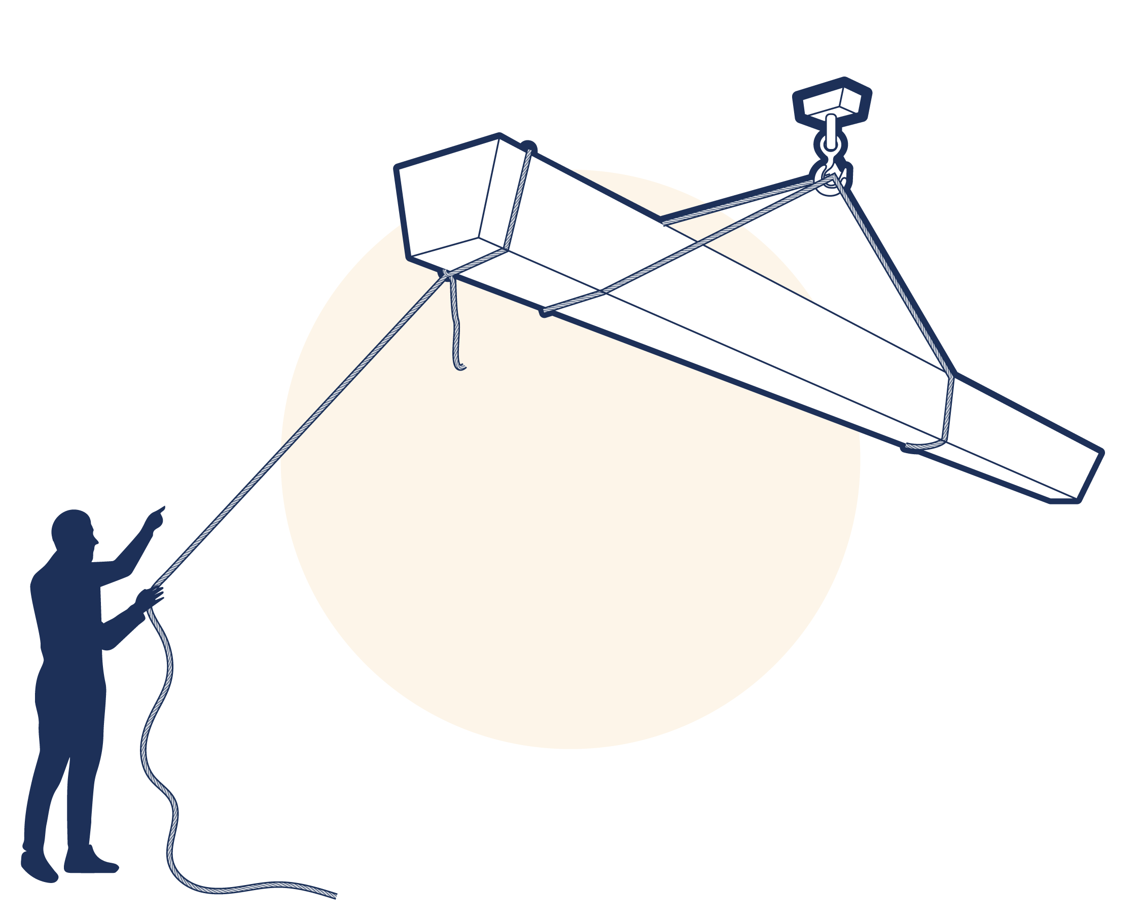
Figure 1.A5.5.5.4-1
A suitable setting down area should be selected before lifting. When lowering, a trial set down should be made before the slings are released. Make sure that the load is placed on battens, dunnage or packing so that the slings can be readily withdrawn. Trapped slings should never be dragged out from under a load, nor should slings be used to drag a load. (See Figure 1.A5.5.5.4-2 )
The slinger should always be careful not to set the load down on his own toes, another common accident. Having set the load down correctly, the empty sling legs should be manually withdrawn by the slinger and hooked back on to the crane hook or upper terminal fitting to prevent accidental ‘hook-up’ to surrounding objects or striking an individual. (See Figure 1.A5.5.5.4-3 )
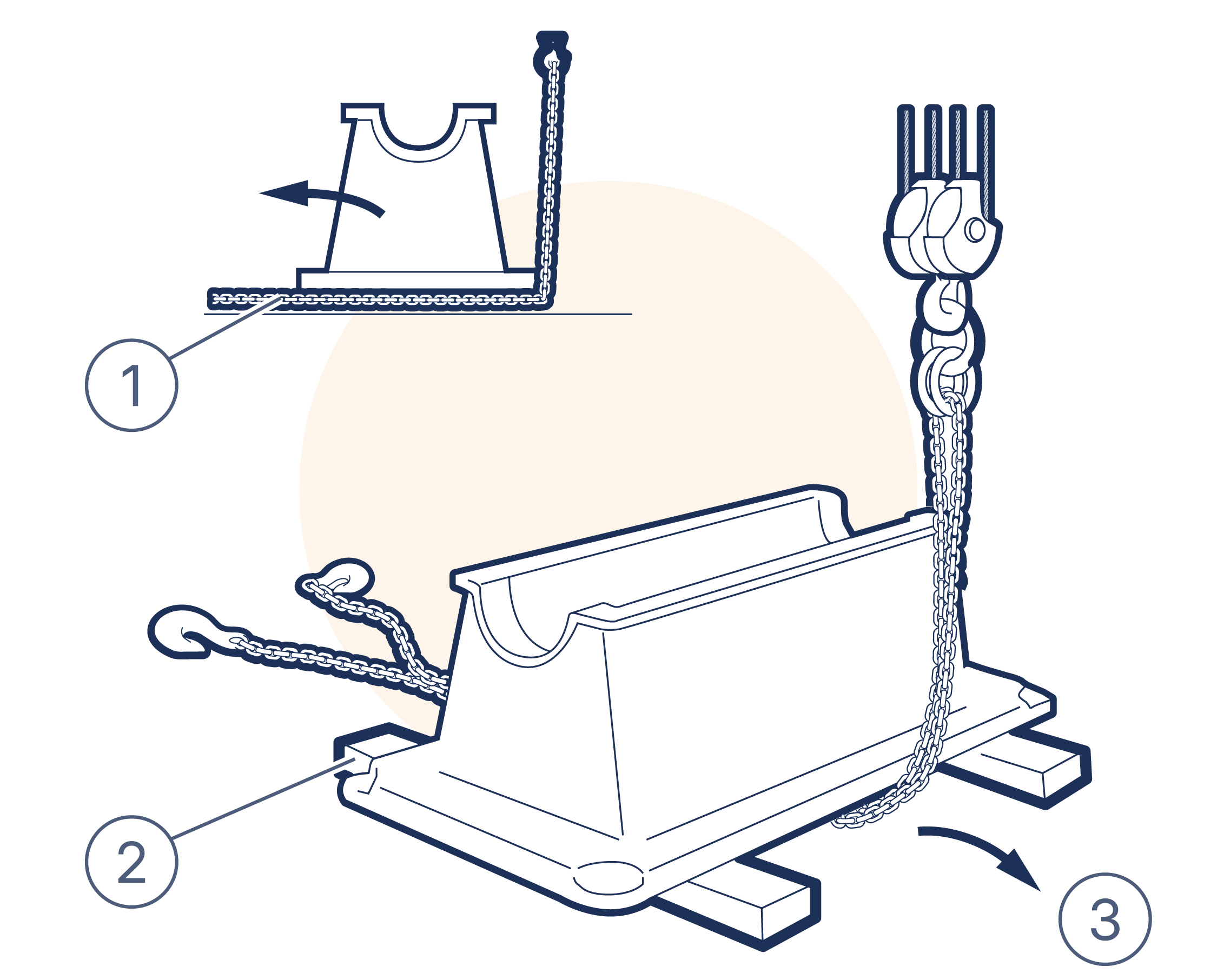
Figure 1.A5.5.5.4-2
Do not pull sling from beneath load
Rest load on timber or other suitable material
Pull by hand
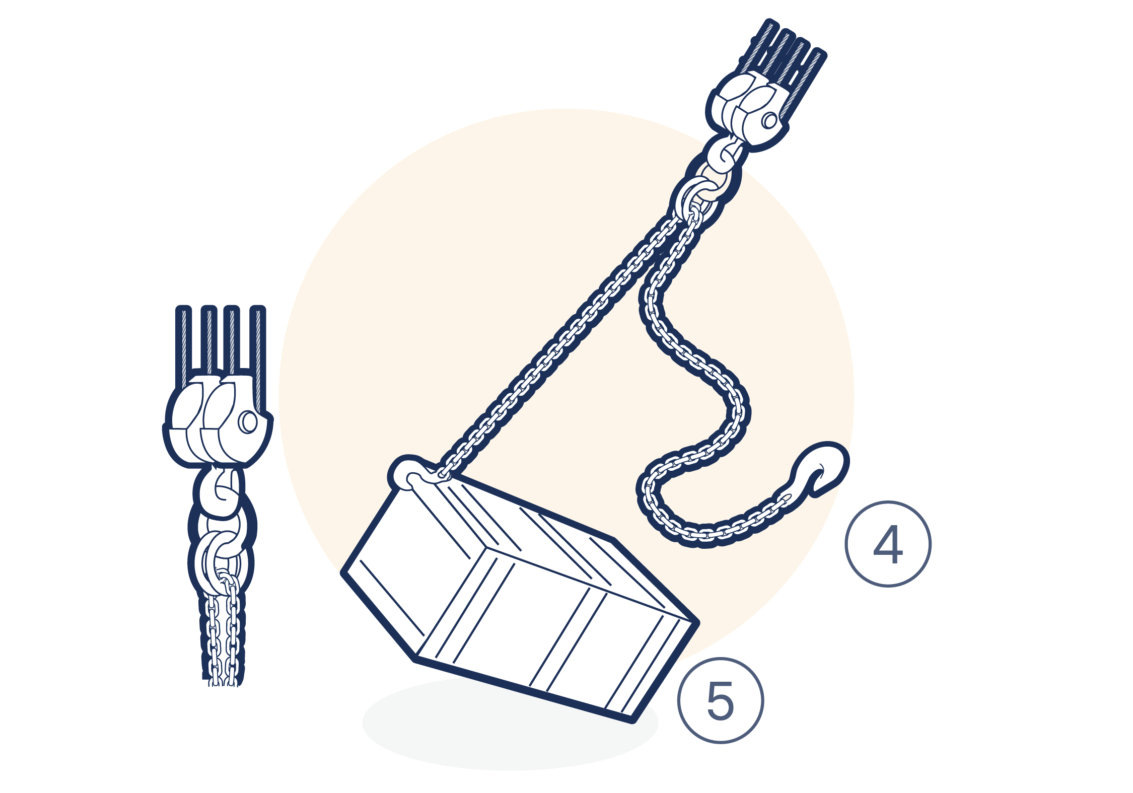
Figure 1.A5.5.5.4-3
Avoid lashing legs
And accidental "hook-ups"
1.A5.5.6 Protection
The need for adequate protection between sling and load is emphasised throughout this code. The objectives of the protection are:
To provide an adequate radius around which a sling may pass without unacceptable loss of load carrying capacity.
To assist the sling in gripping the load.
To prevent damage to the load and sling .
With regard to (1) above, it is important to realise that when a sling is bent around a corner its strength will be considerably reduced. Whilst a small radius will prevent the cutting action of a sharp edge, IT WILL NOT PREVENT THE LOSS OF STRENGTH DUE TO THE SLING BEING LOADED IN THIS WAY.
For example, a chain sling passing around a corner may have one or more links loaded in bending, which could result in premature failure of the chain. (See figure Figure 1.A5.5.6-1 and section 14)
In the case of a wire rope sling, too small a radius would result in a permanent kink (see Figure 1.A5.5.6-2 and section 15) and some of the individual wires being overloaded. Although in both of these examples failure may not occur immediately, permanent damage will have been done which may subsequently result in failure. A radius equal to four times rope diameter will give a reduction in strength of approximately 25%.
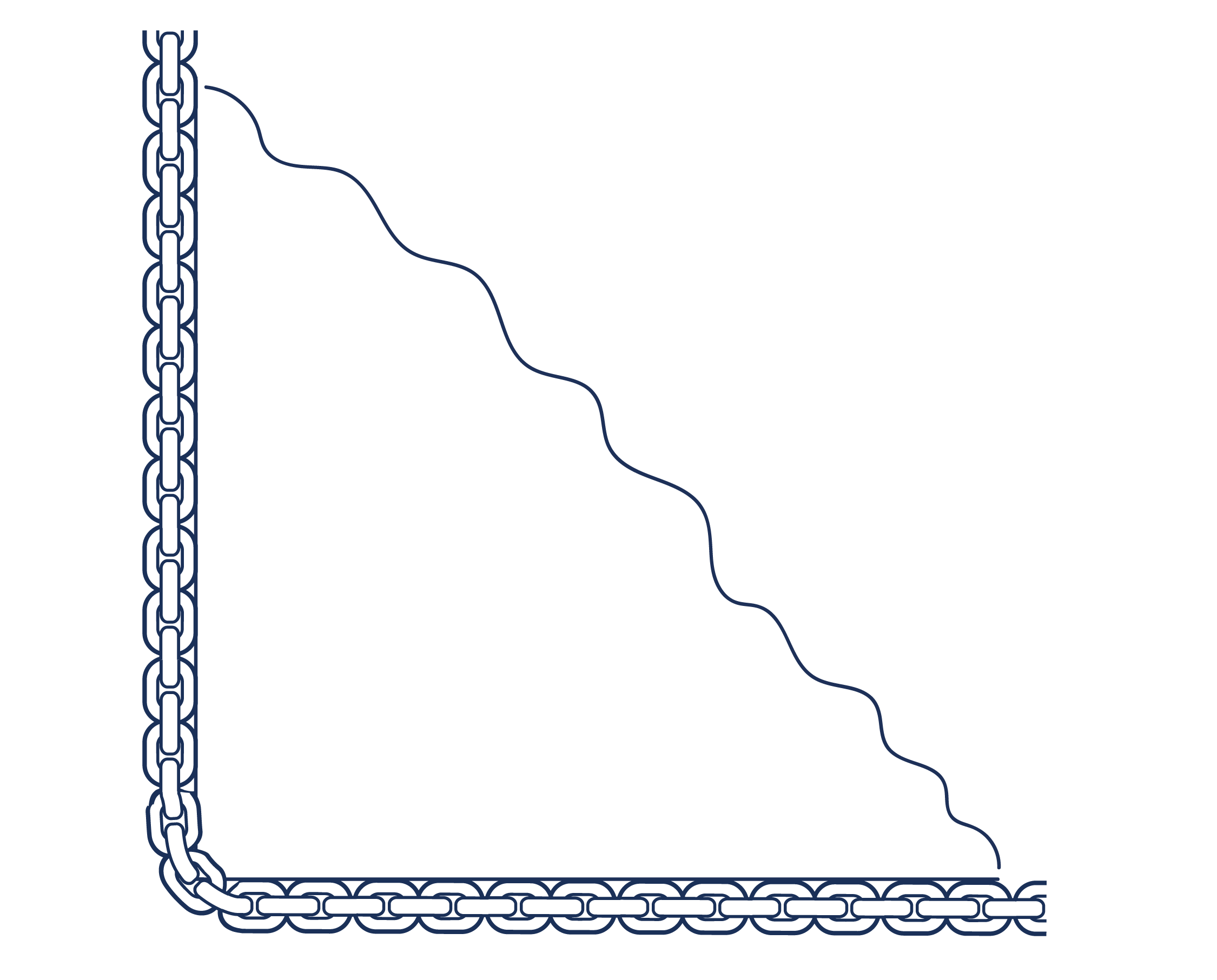
Figure 1.A5.5.6-1
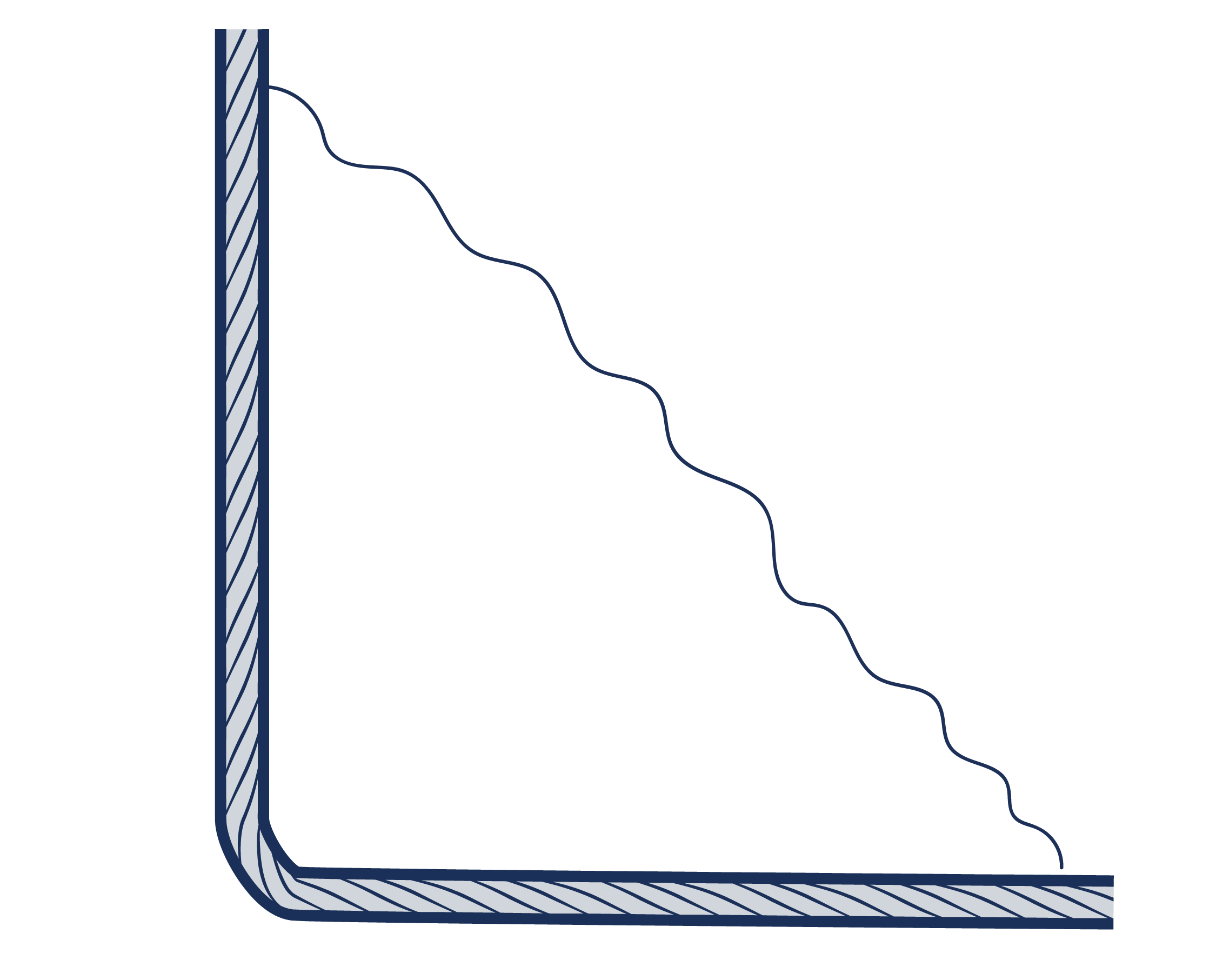
Figure 1.A5.5.6-2
Various materials are suitable for protection. Whatever is used must be capable of taking the crushing forces which will be imposed upon it, and it should be positioned to make best use of its strength. Where a particular load is lifted regularly, purpose designed re-usable packing may be found economical but for general purposes, the operative should have available a good selection of materials according to the nature of the work (e.g. timber blocks, rubber, sections of vehicle tyres, conveyor belts, etc.).
When positioning protection, it is essential to ensure that it will stay in place throughout the lift, as packing which falls or flies out will be a hazard in itself as well as imposing shock loads upon the lifting equipment. It may, therefore, be necessary to provide some independent means of securing the packing in place.
The amount of protection required varies according to the particular situation. The illustrations in Figure 1.A5.5.6-3 , Figure 1.A5.5.6-4 , Figure 1.A5.5.6-5 and Figure 1.A5.5.6-6 provide some examples of good and bad practice.
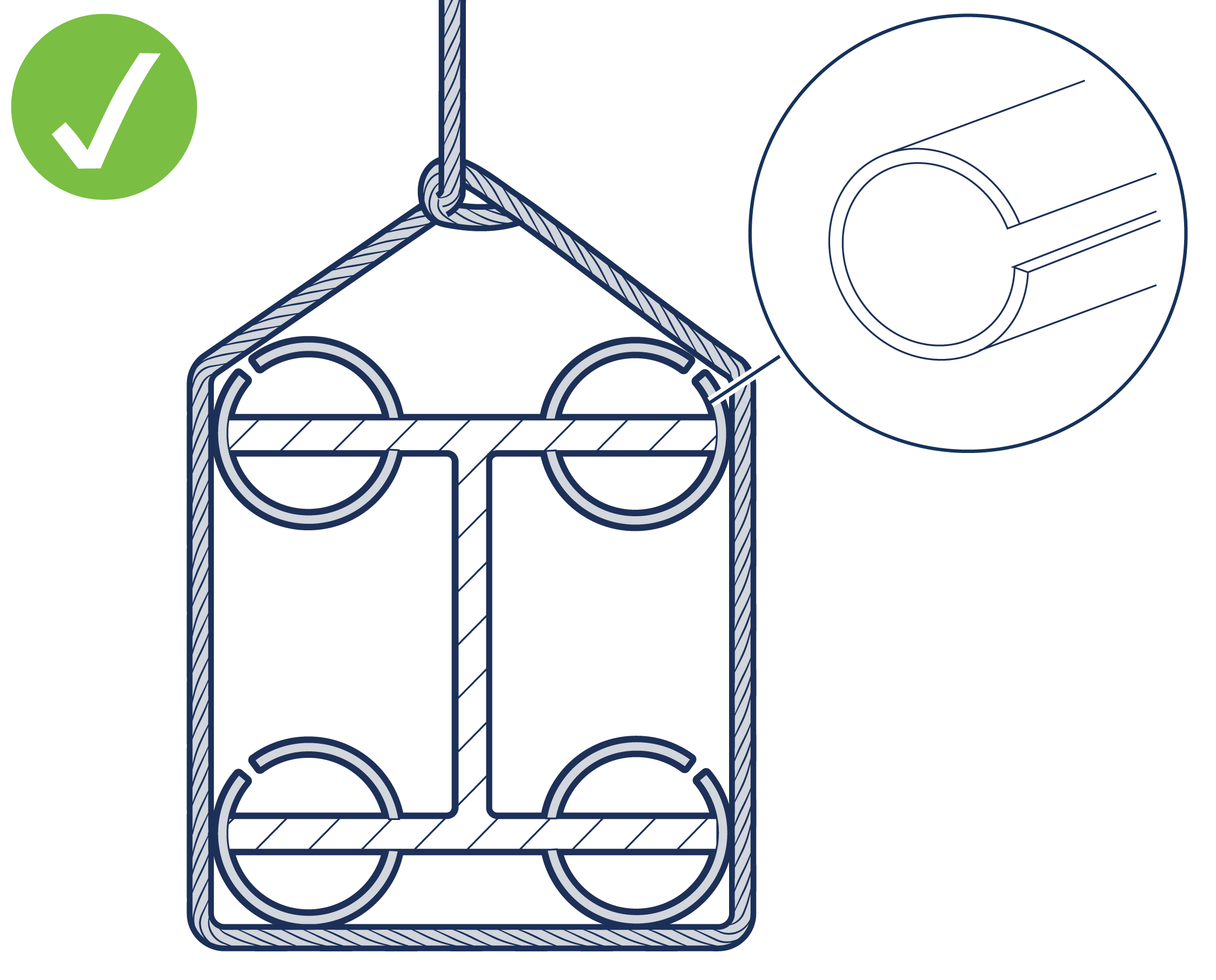
Figure 1.A5.5.6-3 Good standard - adequate radius - no kinking
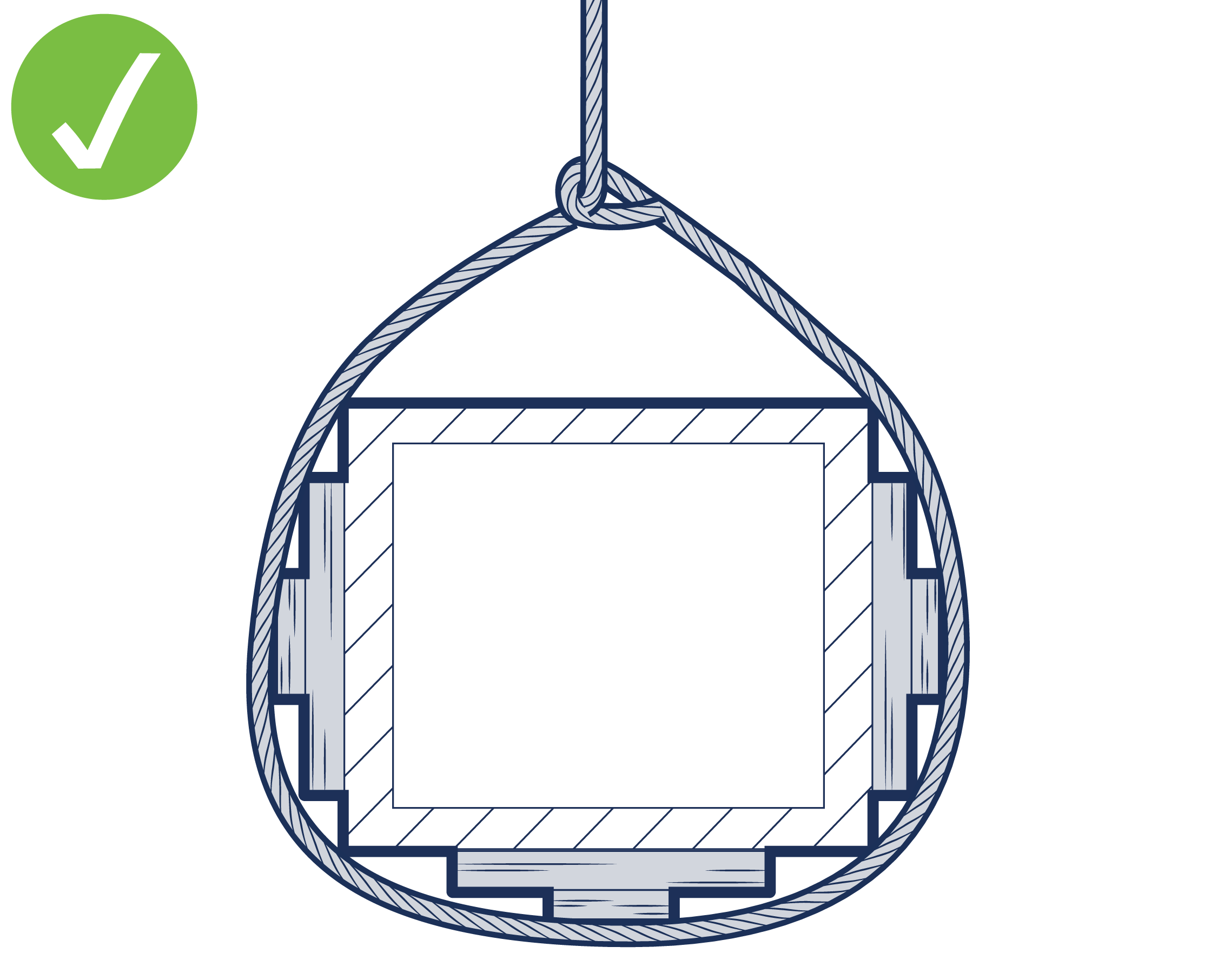
Figure 1.A5.5.6-4 Good standard - adequate radius - no kinking
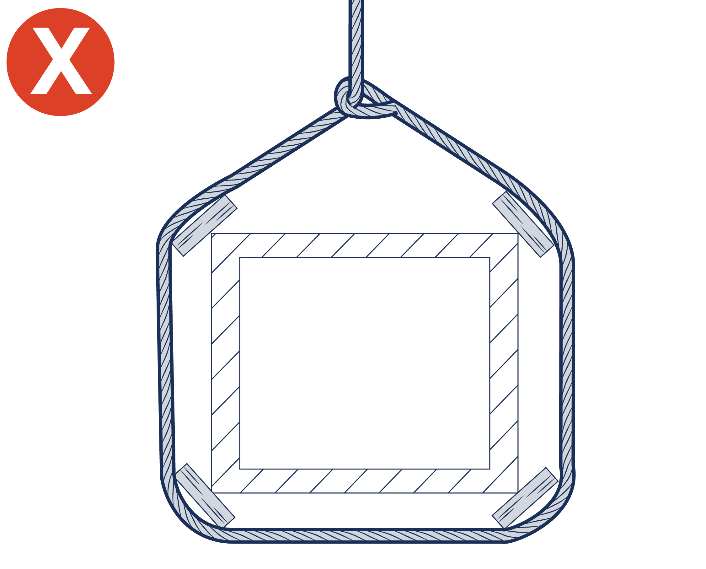
Figure 1.A5.5.6-5 Bad practice - timber packing will split and may fall out
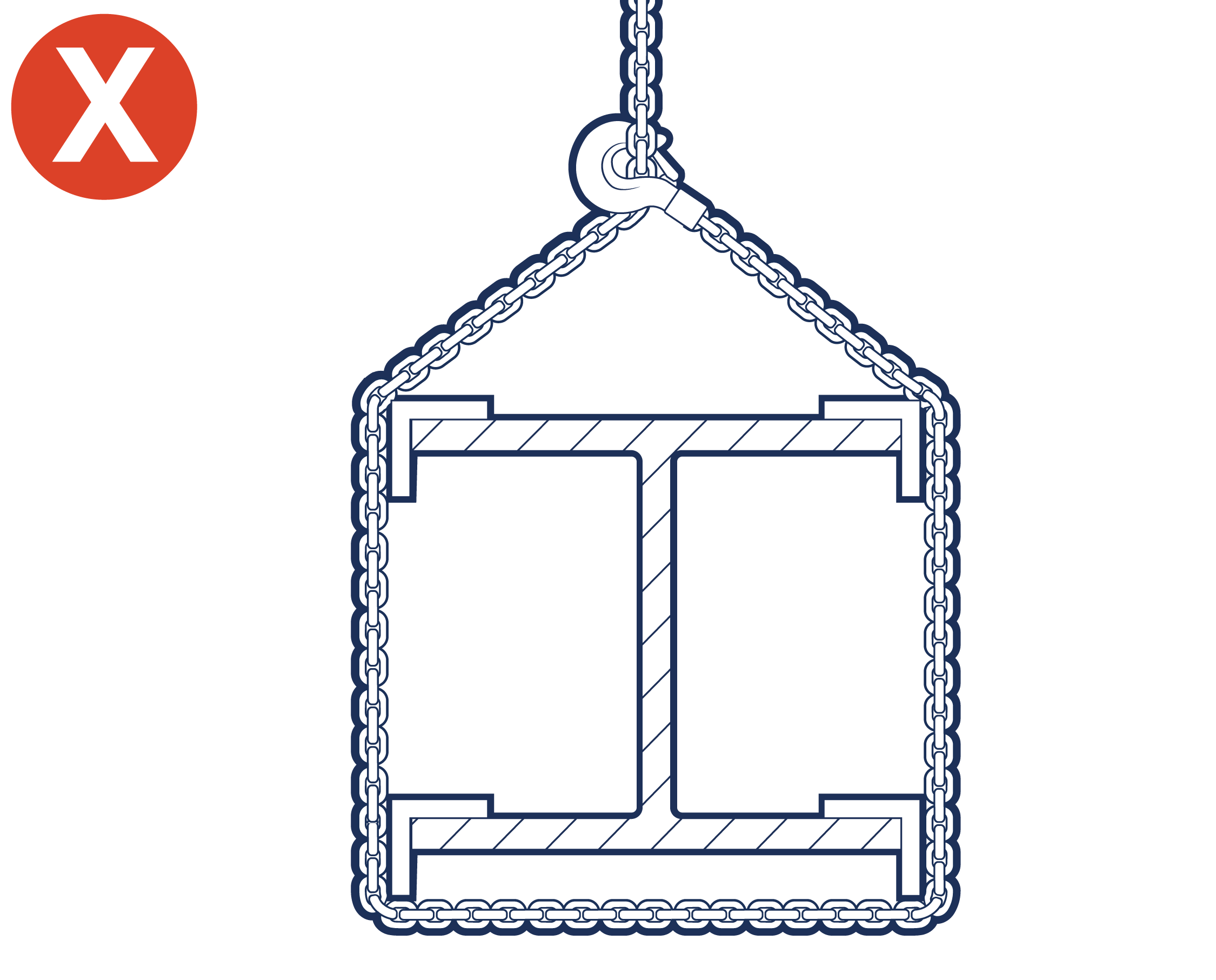
Figure 1.A5.5.6-6 Bad practice - packing ineffective chain links may be bent
1.A5.5.7 Control of Lifting Equipment, Storage, Handling and Inspection
For information on the control of lifting equipment, storage, handling and inspection, see section 1.7 MARKING, STORAGE AND HANDLING and section 1.8 INSPECTION of this code and the section specific to the equipment. Standards, manufacturer’s literature and statutory requirements may also be applicable.
1.A5.5.8 Training
For information on training see section 1.9 SAFE USE OF LIFTING EQUIPMENT of this code.