1.A5.4 PRINCIPLES FOR THE SELECTION OF SLINGS
There are numerous factors to be considered in the selection of a sling for a particular task or range of tasks. These will include sling type (i.e. material) configuration (i.e. number of legs) terminal fittings (e.g. hooks) and environmental conditions.
1.A5.4.1 Sling Types
1.A5.4.1.1 Chain
Chain slings can be supplied as mechanically assembled or welded assemblies, with the former being the most common. The current standards and grades for these slings are listed in SECTION 14 of this code.
Further information on the use of chain slings is given in section 14.1 FOREWORD of this code.
1.A5.4.1.2 Wire rope
Wire rope slings are available in several different grades, constructions and terminated by various means. The current standards for wire rope slings are detailed in section 15 of this code.
Further information on the use of wire rope slings is given SECTION 15 of this code.
1.A5.4.1.3 Fibre ropes
Fibre rope slings are generally available in a range of natural and man-made fibres and should be purchased to the applicable national standards, for full standards listings and available materials, please refer to SECTION 18 - FIBRE ROPE SLINGS of this code.
Further information on the safe use of fibre rope slings is givenSECTION 18 - FIBRE ROPE SLINGS of this code.
1.A5.4.1.4 Webbing
Flat woven webbing slings should always be purchased in accordance with the nationally adopted and current product standards, refer toSECTION 16 for specific standard details. They are manufactured in a similar variety of textile materials to fibre ropes.
Further information on the safe use of webbing slings is given in SECTION 16 of this code.
1.A5.4.1.5 Roundslings
Roundslings are endless textile slings and should always be purchased in accordance with the nationally adopted and current product standards.
Further information on standards and the use of roundslings is given in sectionSECTION 17 - MAN-MADE FIBRE ROUNDSLINGS of this code.
1.A5.4.2 Sling Configurations
Each of the different material types of sling described in section 1.A5.4.1 Sling Types and the respective specific sections of this code may be encountered in any one of five different basic configurations for general purpose slings, i.e. single leg, two leg, three leg, four leg and endless slings. Selecting a suitable sling configuration depends mainly on the type of load. Examples of different types are provided below. For abnormal loads special slings are available and recommended. Users should seek the advice of their LEEA member supplier if in doubt.
1.A5.4.2.1 Single leg sling
A single leg sling may be used to connect a lifting appliance to a load with a single lifting point such as the eyebolt on an electric motor. (See Figure 1.A5.4.2.1-1 ) It may also be used in choke hitch either by back hooking or reeving one end of the sling through the other. (See Figure 1.A5.4.2.1-2 )
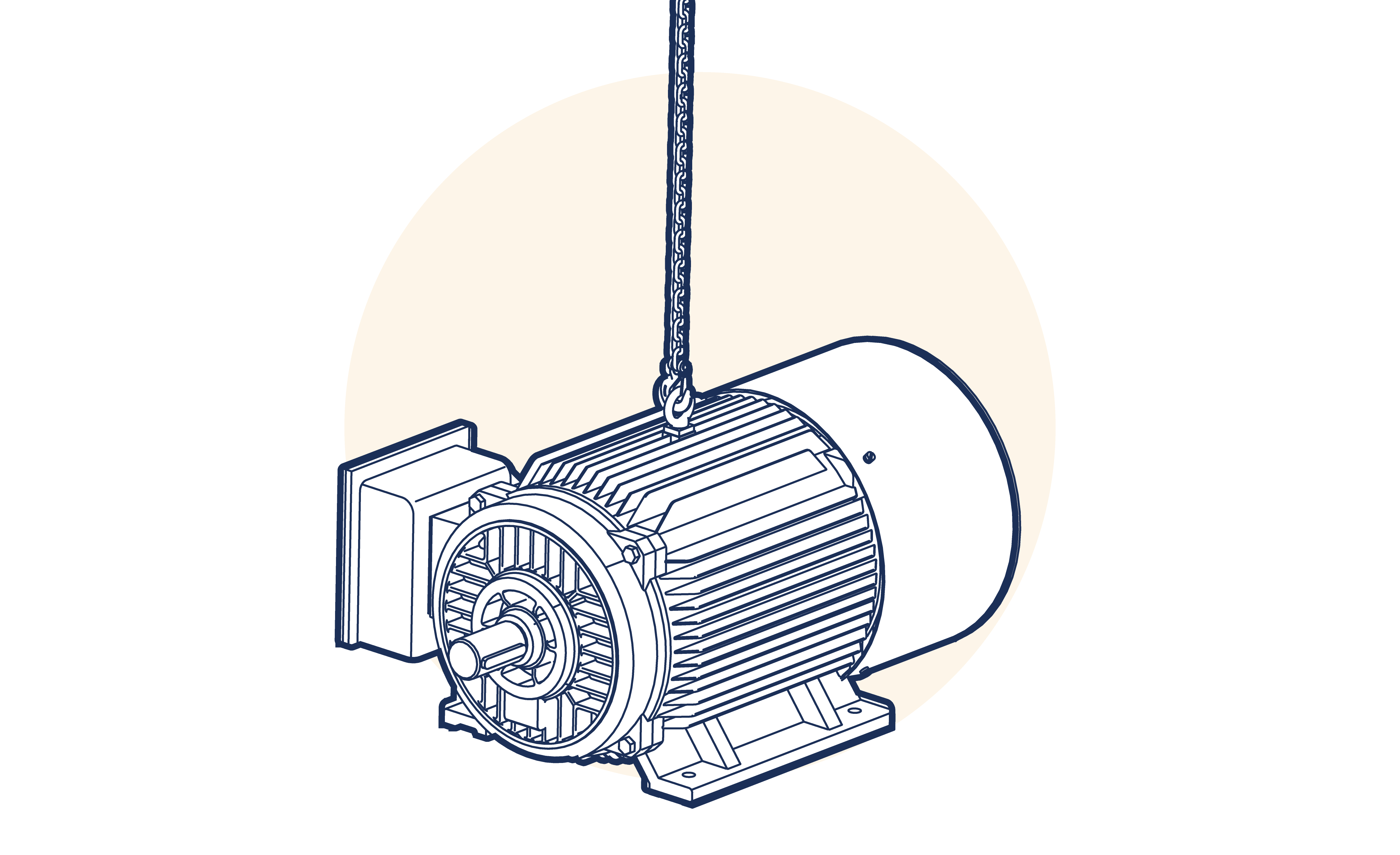
Figure 1.A5.4.2.1-1
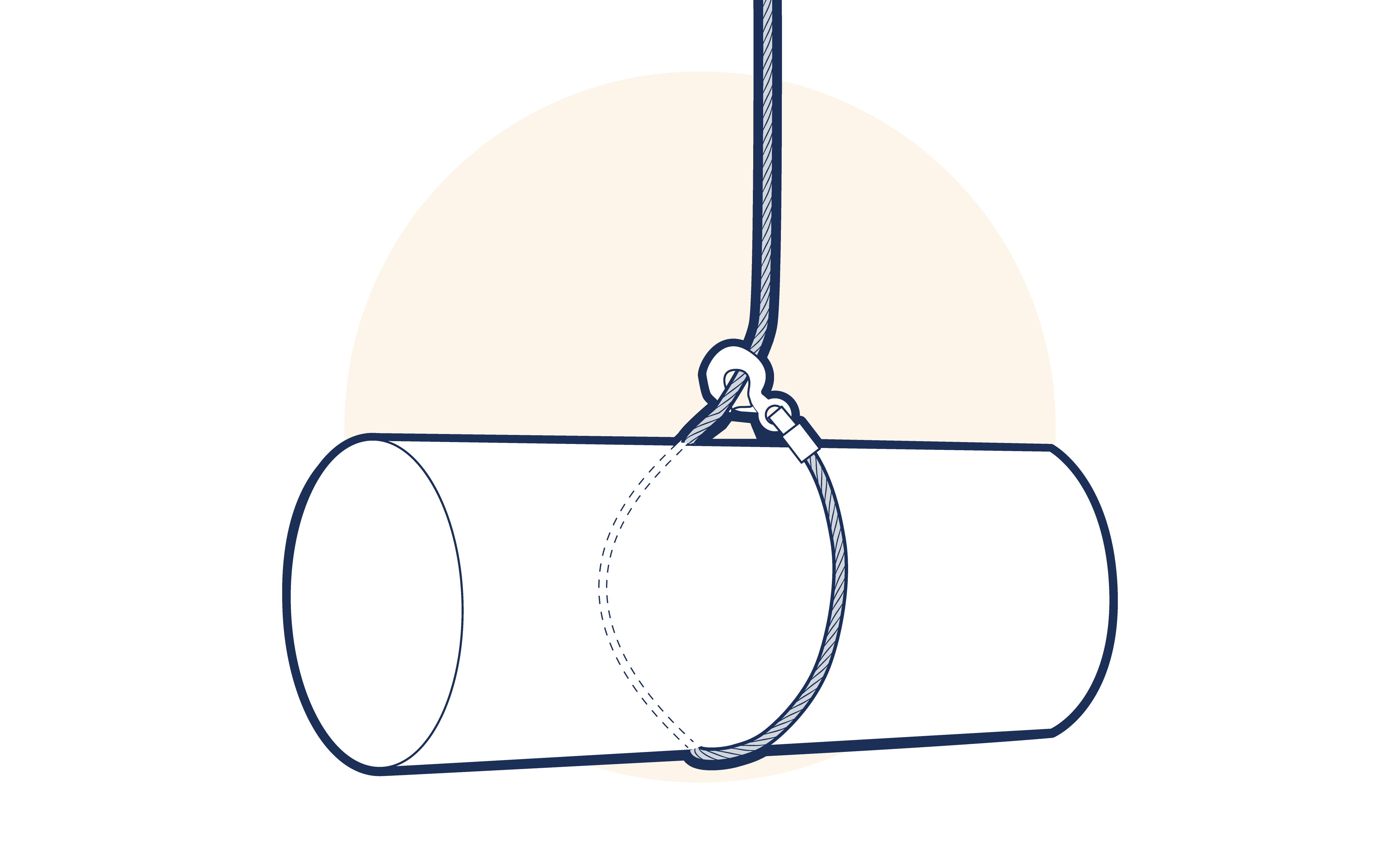
Figure 1.A5.4.2.1-2
Two identical single leg slings may be used in combination to form, in effect, a two leg sling. (See Figure 1.A5.4.2.1-3 ) Care is necessary to ensure that the hook of the lifting appliance is not overcrowded and it is recommended that the upper end of the sling legs to be connected by a shackle or link. (See Figure 1.A5.4.2.1-4 ) Where this is done the legs must be symmetrically disposed and the angle of a leg should not exceed 45° to the vertical.
The method of attaching the slings to the crane hook should ensure that the sling eyes or links are not damaged. Two single leg slings used as a two leg sling must be treated as a two leg sling for rating purposes. The combined SWL when the legs are at an angle between 0 and 45° to the vertical (0 to 90° included angle) is 1.4 times the SWL of the single leg.
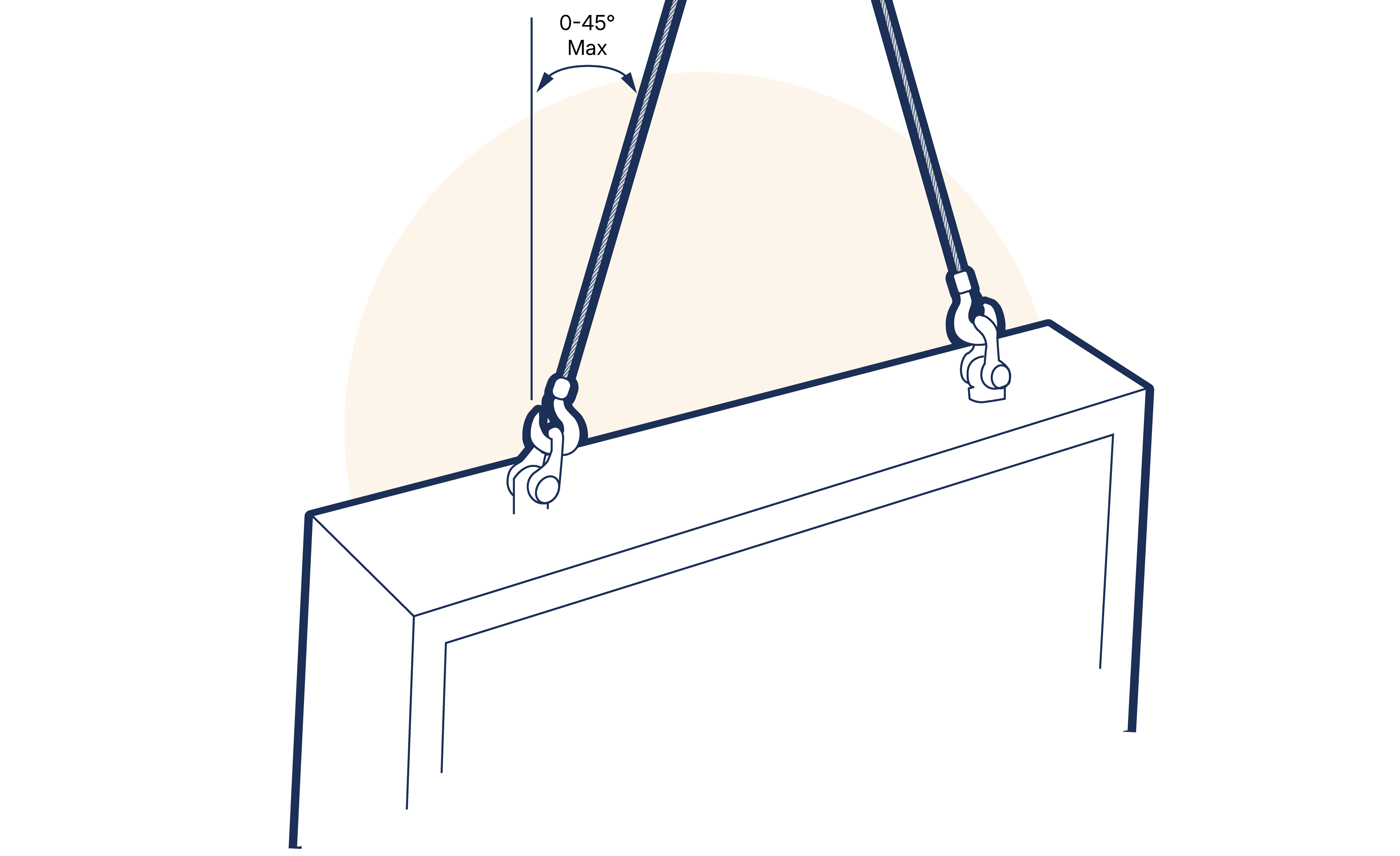
Figure 1.A5.4.2.1-3
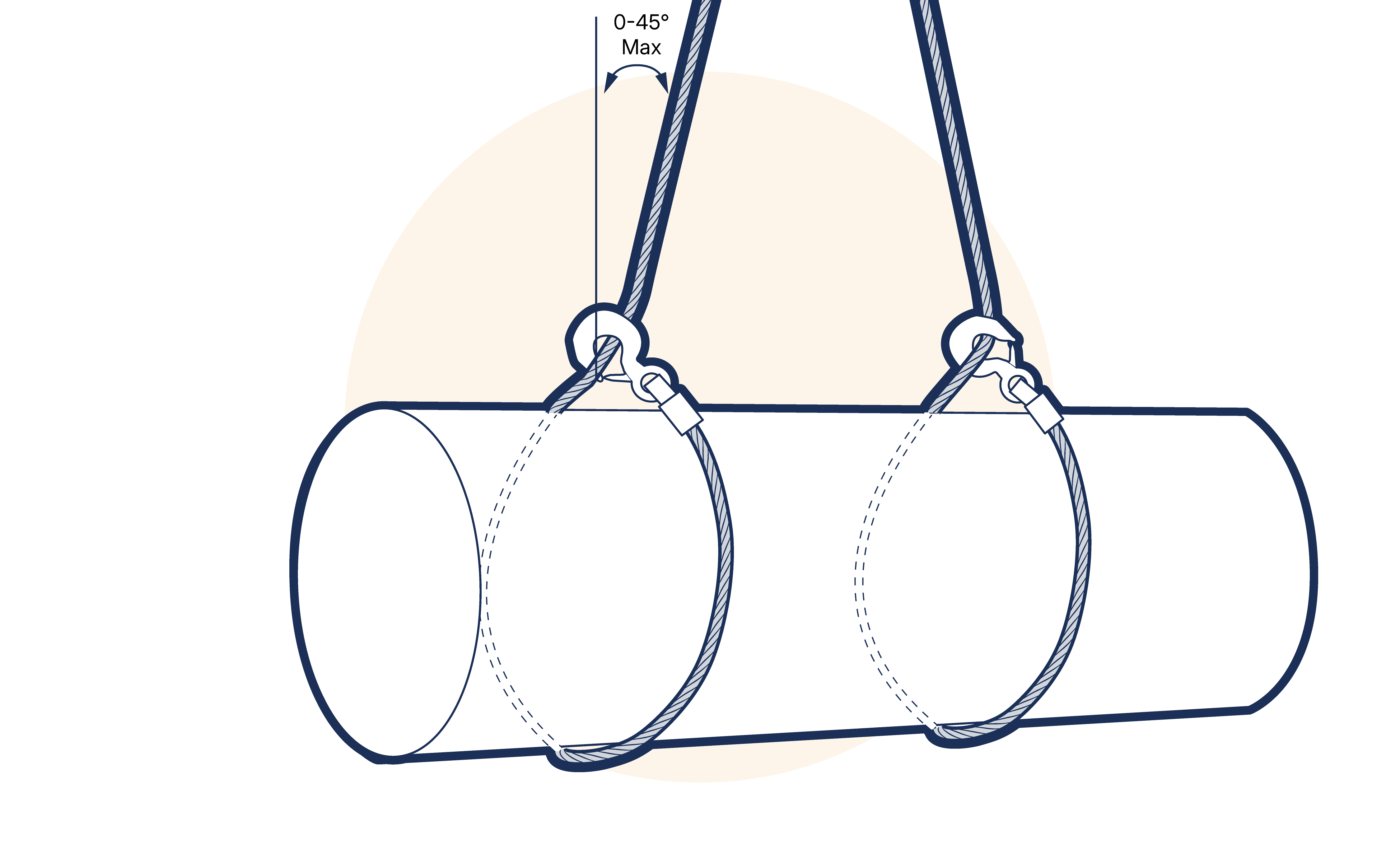
Figure 1.A5.4.2.1-4
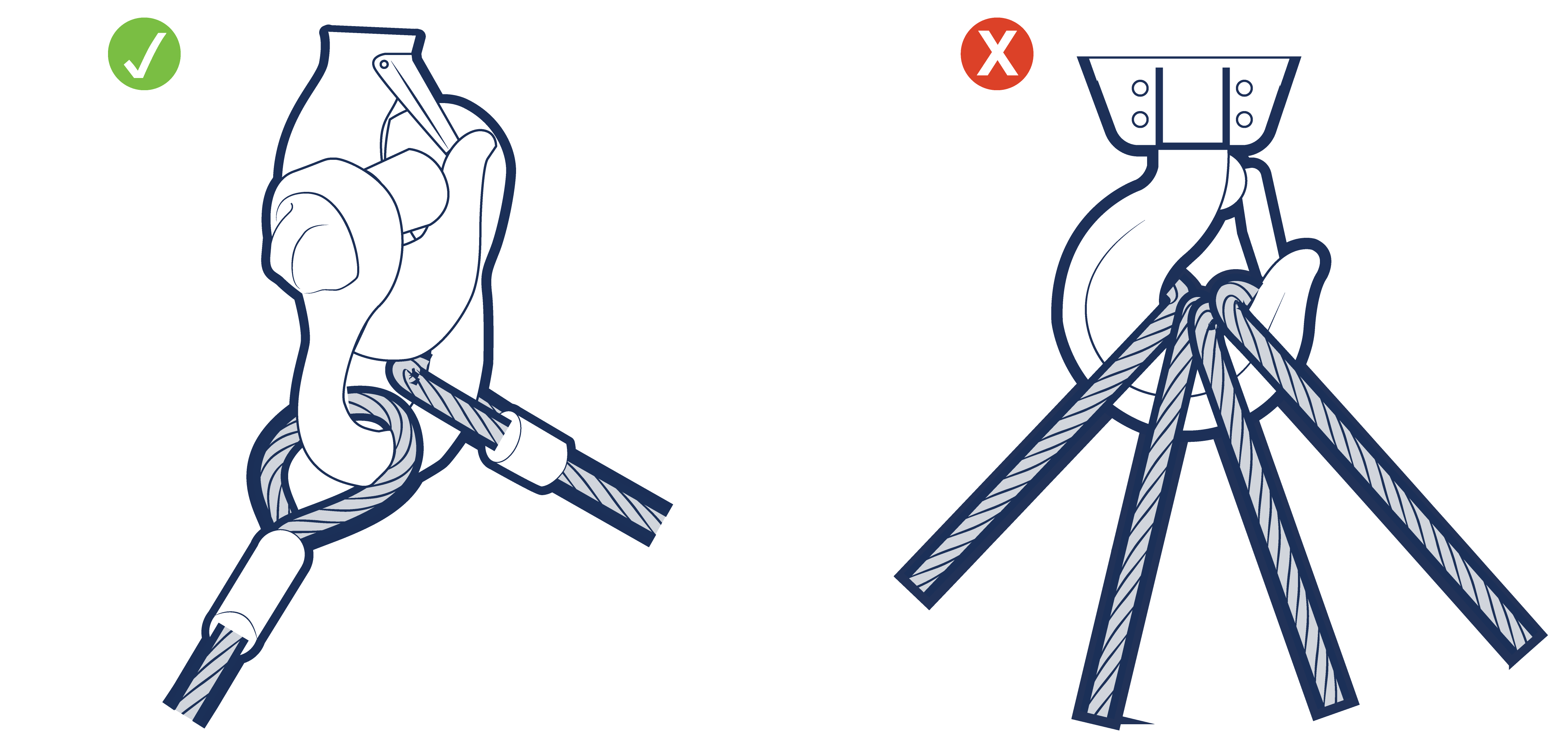
Figure 1.A5.4.2.1-5
1.A5.4.2.2 Two leg sling
A two leg sling comprises two legs permanently connected at their upper ends by a suitable link and marked as an assembly. Two leg slings may be used to handle a wide range of loads. (See Figure 1.A5.4.2.2-1 Figure 1.A5.4.2.2-2 )
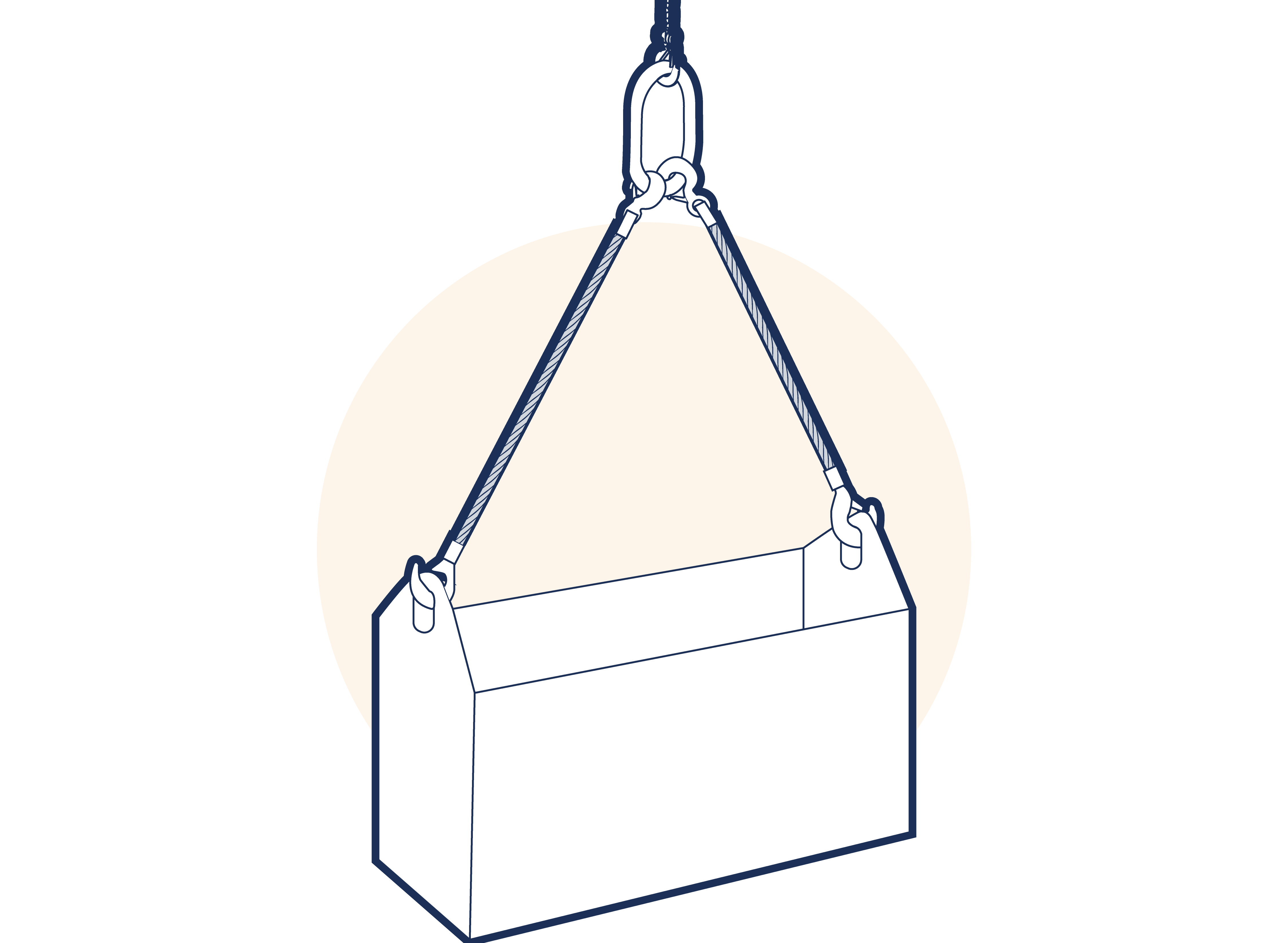
Figure 1.A5.4.2.2-1
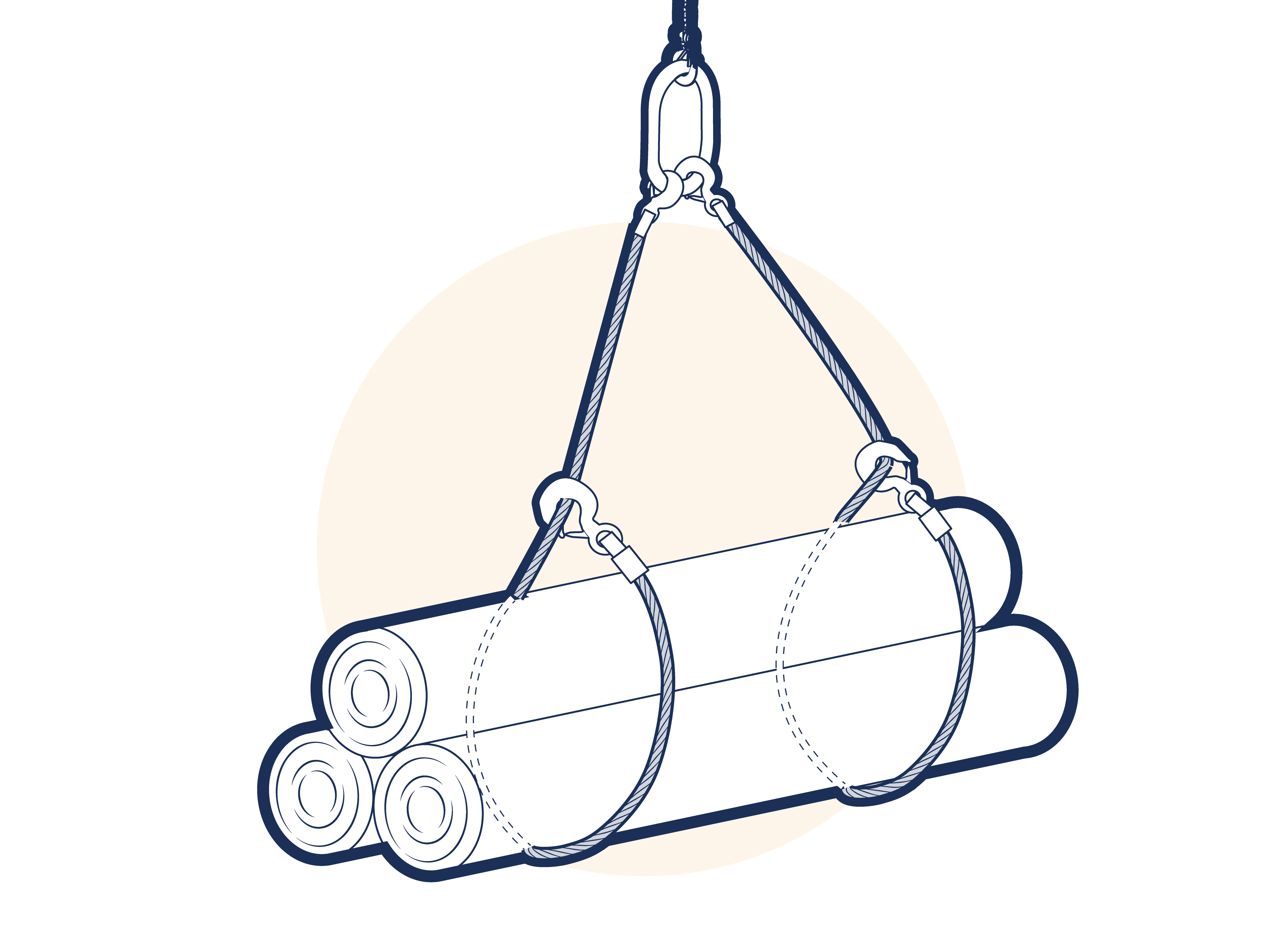
Figure 1.A5.4.2.2-2
1.A5.4.2.3 Three leg sling
A three leg sling comprises three legs permanently connected at their upper ends by a suitable link assembly and marked as an assembly. Three leg slings are commonly used to handle circular or irregularly shaped loads where the legs can be equally spaced. (See Figure 1.A5.4.2.3-1 )
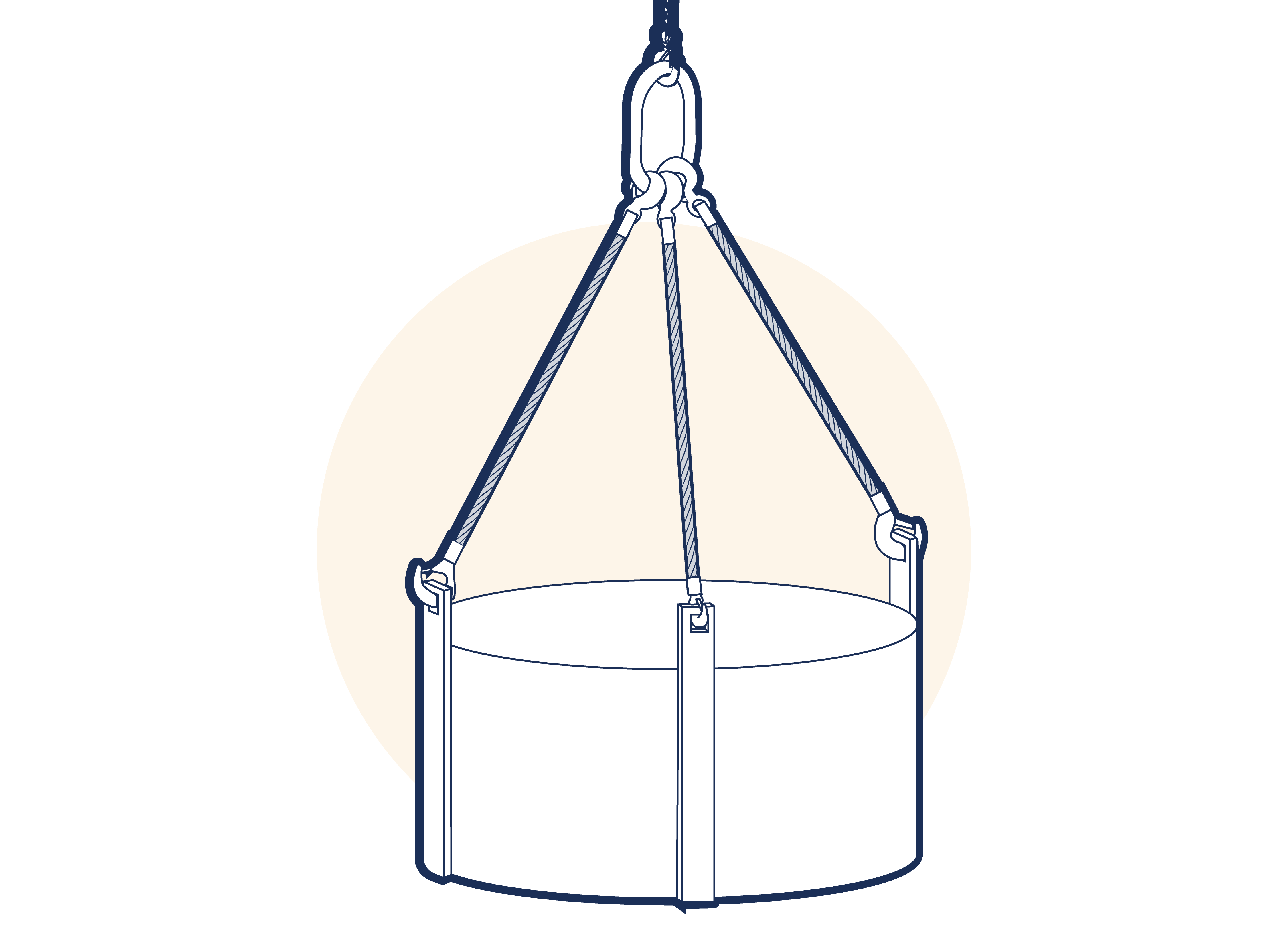
Figure 1.A5.4.2.3-1
1.A5.4.2.4 Four leg sling
A four leg sling comprises four legs permanently connected at their upper ends by a suitable link assembly and marked as an assembly. Four leg slings are mainly used to handle square or rectangular (four cornered) loads. (SeeFigure 1.A5.4.2.4-1 )
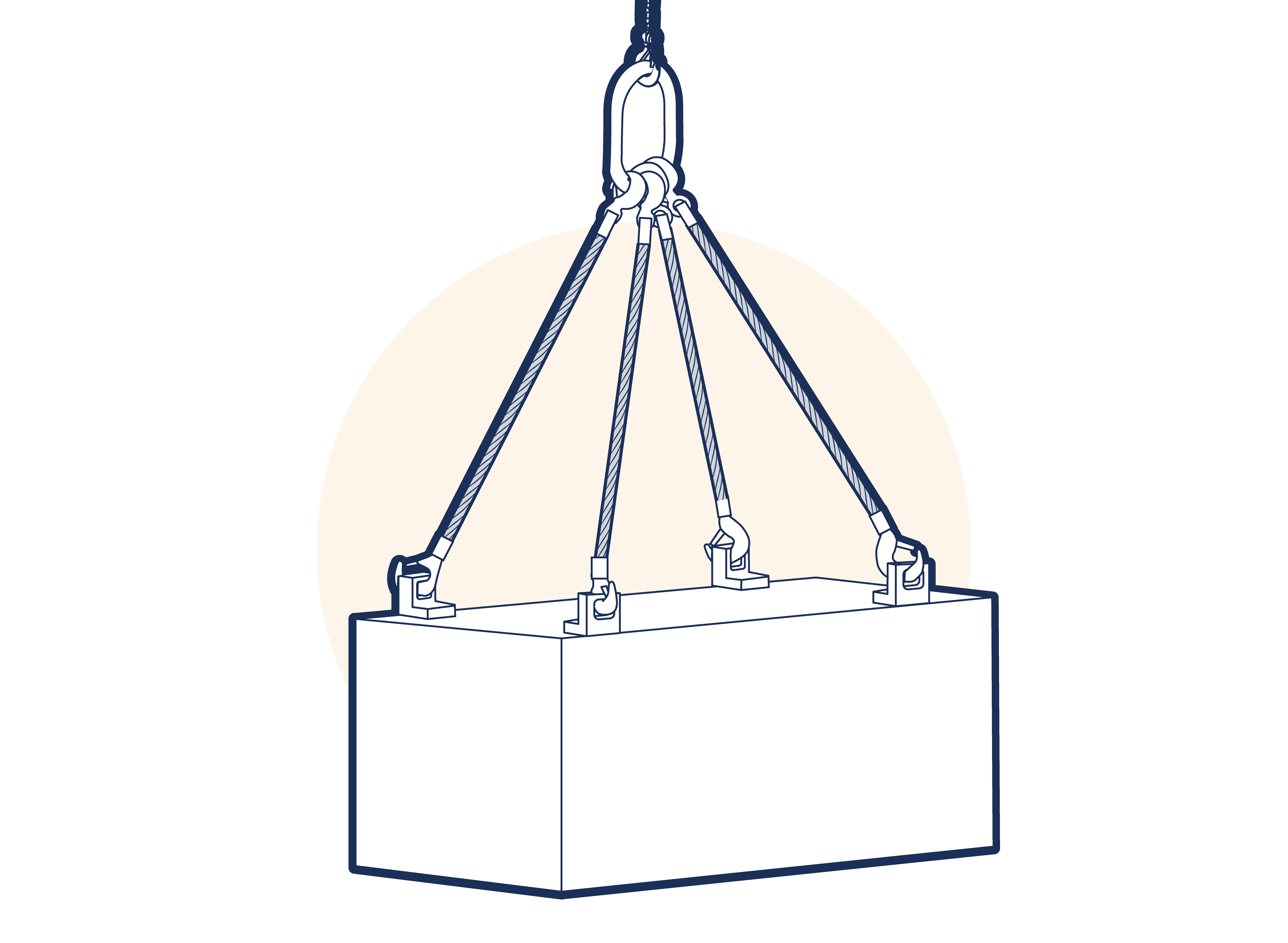
Figure 1.A5.4.2.4-1
1.A5.4.2.5 Endless sling
Although there are some exceptions, an endless sling is usually used in choke hitch. (See Figure 1.A5.4.2.5-1 )
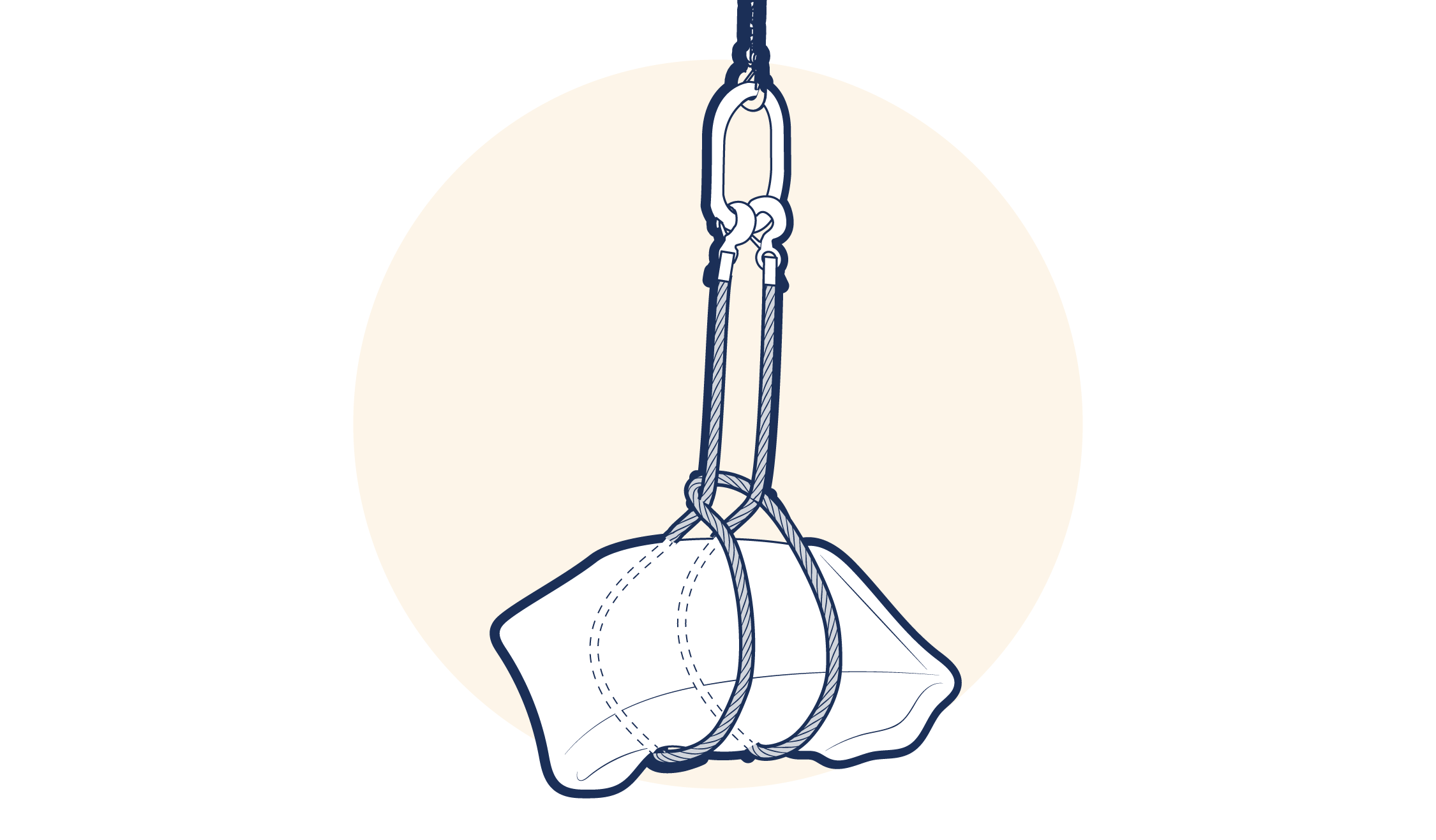
Figure 1.A5.4.2.5-1
1.A5.4.3 Methods of Rating Lifting Slings
1.A5.4.3.1 Multi-Leg Slings: Load Angles and Rating Methods
When a multi-leg sling is used with the sling legs at an angle, the load in the individual sling legs will increase as the angle to the vertical (included angle between the legs) becomes greater. This is illustrated in Figure 1.A5.4.3.1-1 .
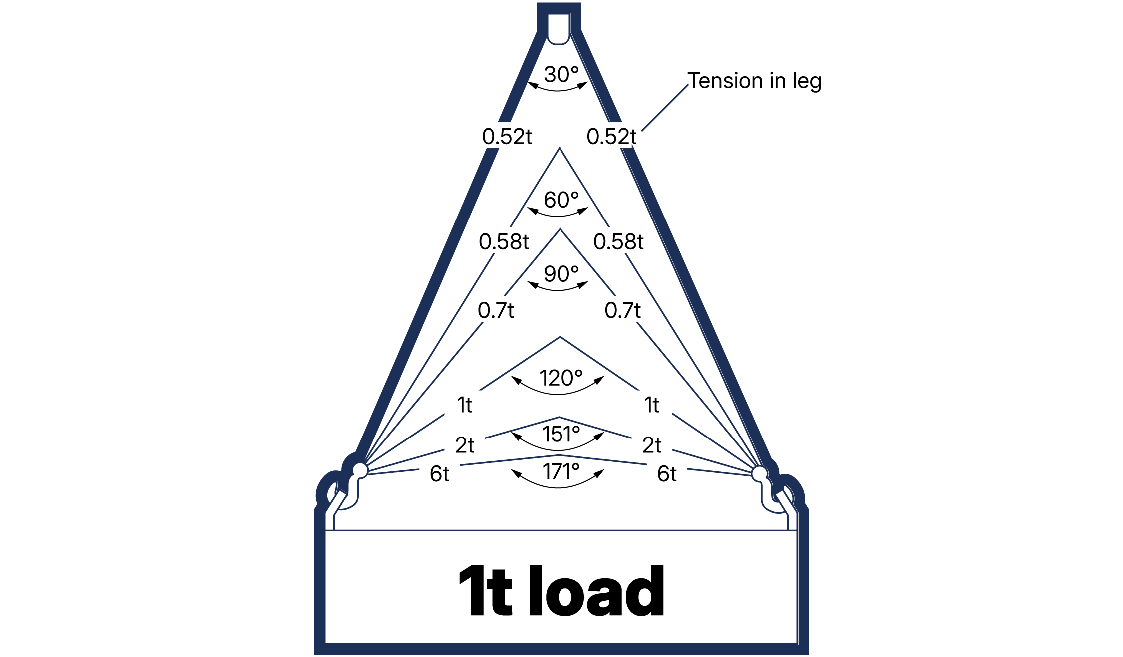
Figure 1.A5.4.3.1-1
Traditionally the angle has been measured as the included angle α (alpha) between the legs of a two leg sling and between the diagonally opposite legs of a four leg sling. As three leg slings do not have an ‘opposite’ leg it was taken for these as twice the angle to the vertical. This assumed that the legs would be symmetrically disposed in plan. (See section 1.A5.5.2 Rating Assumptions) In order to emphasise that the angle of each leg to the vertical affects the share of the load it will carry and to remove the anomaly with three leg slings. It should therefore be noted that the traditional method of measuring the included angle α (alpha) between the legs of a two leg sling and between the diagonally opposite legs of a four leg sling is no longer recommended by this code and the angle between the leg and the vertical β (beta) should be used instead.
It is possible that some multi-leg slings in service will be marked with the rating expressed at the included angle or range of angles, e.g. 0-90°. However, based on the above for this code the rating will be expressed at the range of angles of a leg to the vertical, e.g. 0-45°. It should be noted that this is based on new methods that have been used in previous versions of this code however, as the code is written to reflect equipment that will be found in service and the acceptance that some geographical regions have not yet adopted the new approach, reference is also made to the included angle. If a sling is to be used safely, allowance must be made for this angle and this is achieved by rating the sling in one of two ways. This matter is discussed in some detail in the following section, which specifies the methods and factors to be used in calculating the SWL. The two methods of rating are often known as the ‘uniform load method’ and the ‘trigonometric method’.
1.A5.4.3.2 Uniform Load Method
The uniform load method is the simpler option, having inherent safety advantages, permitting only one working load limit up to an angle of 45° to the vertical (90° included angle) and a reduced working load limit at angles between 45° and 60° to the vertical (90° and 120° included angle). This is the recommended method which should be used for all multipurpose slings Working load limits are derived from the following:
Single leg sling = 1.0 x WLL of a single leg
Two leg sling 0-45° (included angle 0-90°) = 1.4 x WLL of a single leg
Two leg sling 45°-60° (included angle 90° -120°) = 1.0 x WLL of a single leg
Three and four leg sling 0-45° (included angle 0-90°) = 2.1 x WLL of a single leg
Three and four leg sling 45°-60° (included angle 90° -120°) = 1.5 x WLL of a single leg
Standards where the uniform load method has been used, rate a multipurpose four leg sling at the same working load limit as a three leg sling of the same size and grade. This is on the assumption that the load might be taken by only three of the four legs. However, some national standards have now been amended such that they work on the assumption that the load may be carried by two of the legs.
Some standards do not recommend the rating of three leg slings at included angles greater than 90°. This is due to the possible hazard of a user assuming that the ‘included angle’ referred to the angle between the legs of the sling instead of twice the angle of a leg to the vertical. Where slings are rated and marked on the basis of the angle to the vertical this hazard does not exist.
1.A5.4.3.3 Trigonometric Method
The trigonometric method provides for a variation in the working load limit as the angle to the vertical (or the angle between the sling legs) varies. This method is the one which was previously used in many standards, but in order to use it for multipurpose applications, the operative must calculate the SWLs at various angles for each size of chain, rope, etc. It also requires the operative to be trained in determining a range of angles and has the inherent danger that if misjudged the sling may be overloaded. Reference to drawings are therefore recommended.
Although the uniform load method was introduced to some standard practices, some manufacturers continue to rate and mark multipurpose slings by the trigonometric method. Slings intended for multipurpose use marked this way will not comply with those standards that have adopted the uniform load method and it is strongly recommended that this method should be used only for slings designed for a single purpose or in accordance with the applicable national standards that permit it. Working load limits are derived from the following:
Single leg sling = 1 x WLL of a single leg
Two leg sling = 2 x WLL of a single leg x cos β
Three leg sling = 3 x WLL of a single leg x cos β
Four leg sling = 4 x WLL of a single leg x cos β
Where β is equal to the angle between the sling leg and the vertical (i.e. half the included angle α).
In the case of a single purpose four leg sling designed for exclusive use in an application where the load will clearly be shared by the four legs, it is permissible to calculate the working load limit on that basis.
1.A5.4.3.4 Advantages of the Uniform Load Method
The uniform load method simplifies matters by removing the need for calculations and reducing the need for the operative to determine angles. Whilst the uniform load method of rating is most easily applied to equipment such as multi-leg slings, it may, with advantage, also be applied to such items as, for example, eyebolts when used in pairs.
1.A5.4.3.5 Recommendation of the Uniform Load Method
Many national and international standards are now in favour of the uniform load method, largely on the grounds of safety and simplicity. However, this does not exclude the trigonometric method when working to national standards that allow it within their scope or with justified reason to deviate from the uniform load method. This code recommends that the uniform load method is used for all multipurpose applications and that the trigonometric method should be restricted to slings designed and used for a single purpose.
1.A5.4.3.6 Use of Consistent Rating Methods
It should be clearly understood however that whilst equipment designed to be used under the trigonometric method may be re-rated and marked according to the uniform load method, the reverse is NOT always possible and may be dangerous. It is therefore recommended that, to avoid confusion, all items of a given type (e.g. all chain slings) at the location should be rated and marked by the same method.
1.A5.4.3.7 Re-Marking and Training for Rating Methods
The method of expressing and marking the rating at the angle to the vertical also raises the question of how a user, with existing slings rated by the uniform load method but marked with the ‘included angle’ will avoid confusion when introducing new slings marked with the ‘angle of inclination’. It is LEEA’s recommendation that the user should consider whether a programme of re-marking is worthwhile, bearing in mind the expected life of the slings and respective national requirements. Regardless of whether existing slings are re-marked, there is a possibility that both systems will be encountered in use. We therefore further recommend that all operatives are made aware and trained to recognise the differences.
1.A5.4.4 Sling Terminations
Slings may be terminated in a variety of ways and the specific sling sections of this code identify the common types used
1.A5.4.5 Factors Influencing Choice Of Sling
If faced with lifting a fragile load, for example a grand piano, a different type of sling would be selected (probably a flat woven webbing sling) from that chosen for lifting hot metal ingots (probably a chain sling).
The following factors are not necessarily in order of importance, nor do they represent an exhaustive list, but are some of the considerations which may be appropriate in selecting a sling. Users are advised to consult a LEEA member if in any doubt as to the suitability of a sling for any lifting purpose, environment, etc. In making a selection, a balance will be struck between various, sometimes conflicting, considerations and the final decision may be one of several compromise solutions.
1.A5.4.5.1 The nature of the load
According to the nature of the load, the aspects to be considered include the temperature of the load, the presence of sharp edges and polished surfaces. Textile slings are not suitable for a hot load. If the load has sharp edges, chain might be more durable but even so, edge protection will be necessary. If the load is polished or delicate in some other way, then a flat woven webbing sling, a roundsling or fibre rope sling is likely to be best.
1.A5.4.5.2 The environment in which the sling operates
Hot, corrosive and outdoor environments might be encountered. If the atmosphere is hot, e.g. near a furnace, a chain sling is likely to be more suitable. See section 14.4.3 Sling Construction of this code.
If a corrosive environment is involved, e.g. use in a plating shop, then this is a complex problem and specialist advice should always be sought. It should also be remembered that laundries, swimming baths, pumping stations, sewage works, etc., can also give rise to corrosive conditions.
If outdoor use is involved, then natural fibre ropes are liable to rot and mildew and ungalvanized wire ropes to corrode. Marine conditions, atmospheric pollution, construction sites involving rock, mud, etc., will all aggravate outdoor environmental problems.
Natural fibre ropes are not recommended for use in chemical environments. Man-made fibre ropes have varying resistance to chemicals, e.g. acids, alkalis and solvents. Textile slings are prone to deterioration at high temperatures. Man-made fibres rarely show a sharp melting point; they will either soften over a range of temperatures or they will char or decompose before melting.
1.A5.4.5.3 Handling of the sling
Weight, flexibility, hand contact and length adjustment are some of the factors likely to be important when handling the sling. Textile slings are lightest for a given lifting capacity and may be most suitable where frequent lifting and carrying of the sling is necessary. It should be remembered that chain and roundslings flex easily but cannot readily be pushed through a narrow gap, whereas wire rope may. The effect of hand contact may be a consideration. If so, wire rope or chain is hard and cold to touch, whereas fibre is relatively larger in diameter (useful if pulling is involved) and warmer to handle. Wire rope is liable to broken wires which can injure hands.
1.A5.4.5.4 Durability
Durability can be influenced by factors such as abrasion, storage and repeated use. If abrasion is likely, then chain is most durable and fibre slings are most subject to abrasion damage. If storage for long periods between use is contemplated, a chain sling might be most suitable as other types are prone to various forms of deterioration unless stored under ideal conditions. (See section 1.7.2 Storage and Handling)
1.A5.4.5.5 Extension (stretch)
Man-made fibre ropes may be less suitable if stretch is likely to be a problem, e.g. for precise positioning. It can also be problematic when using two or more slings of different materials