1.A6.4 PRINCIPLES FOR THE SELECTION OF LIFTING APPLIANCES
There are numerous factors to be taken into account when selecting a lifting appliance for a particular task or range of tasks. These will include assessing the operation, deciding on the type of appliance together with any control options and what it will be suspended from. In the case of power operated lifting appliances, the type of power, for example diesel or electric, and, if appropriate, the power feed system will also have to be considered. In the case of mobile cranes sufficient space and support for outriggers. Finally, some additional safety devices may be required to ensure that the system as a whole is safe.
1.A6.4.1 Assessing the Operation
Before considering the type of appliance to be selected, an assessment of the operation is necessary. This must include an appraisal of the operation, other possible uses to which the appliance may be subject to, and an over- view of possible future handling needs. This should also take into consideration any special requirements that may be necessary due to the site, nature of the operation, nature of load or to meet regulations. In this way a list of requirements which need to be met can be drawn up. This should include the following:
Weight of load to be lifted.
Size, shape of load and the centre of gravity.
Nature of load, e.g. if it is hazardous, if it is fragile, etc.
Total height it is necessary to lift the load.
If the load is to be lifted, jacked or pulled. It may be necessary initially to raise the load by jacking to gain sufficient access for other forms of lifting equipment to be employed in the final lifting and/or moving operation.
If it is necessary to move the load, in which plane(s) and over what distance.
Utilization, frequency of use, etc.
If the requirement is temporary or ongoing.
If the equipment will be used solely for the application or if it will be used for other purposes either now or in the future.
If the application does not require the suspended load to be moved, whether a suitable suspension point is available or if it is necessary to provide a means of suspension.
If a structure is required to enable the load to be moved, whether this can be attached to the building members, or if it is to be free standing or if an existing building member is suitable for the purpose.
Headroom available.
If there are any obstructions which may impede the operation.
If the working area is spacious or confined.
If there is an electrical supply available, distance, voltage, phase(s) and frequency.
If the ground is suitable to withstand the applied loads.
If there is an air supply available, pressure and delivery rate.
If the application is indoors or outside.
If the area is affected by any contaminants or substances which may affect the equipment or the operative or that require special measures to be taken.
If the operative needs to be in a remote position.
If any special measures are necessary to comply with regulations which affect the site or operation.
If any special safety requirements need to be met.
this list is not exhaustive.
A further factor in making the final selection will be the cost. To justify the lifting appliance that is finally selected, compromise may be necessary. A well-chosen appliance that is fully utilized or reduces the time taken to perform an operation is easily justified, whereas a costly installation which will stand idle for long periods cannot be. However, at no time must cost be placed before safety. It is important that the selected appliance does not impose unacceptable restrictions on its use. The various options must therefore be carefully taken into account and a balance found so that the selected equipment is safe for the intended use and achieves most or all of the requirements.
1.A6.4.2 Types of Lifting Appliance
In the most basic case, a lifting appliance provides a mechanism which is capable of lifting a load only, e.g. a chain hoist. For most applications, it is necessary to both lift and move loads and many lifting appliances provide a means of doing this. With the use of a simple structure, e.g. a runway with trolley, it becomes possible to move the chain hoist whilst it is supporting the load, but movement is limited to a single plane. A more complicated structure such as an overhead travelling crane or crawler crane allows the load to be raised and moved in any plane.
There are then three distinct areas within the heading of lifting appliances, these are:
Mechanisms, e.g. chain hoist. These are mechanisms which lift the load and/or in some cases provide a means of moving the load when used in conjunction with other appliances.
Static structures which in themselves are incapable of carrying out a lifting operation unless fitted with a mechanism, e.g. mobile supporting structure. These are structures which provide a means of supporting a lifting mechanism and may provide a track on which the machine can move in a single plane.
Moving structures which when fitted with a mechanism are capable of carrying out lifting and moving operations in any plane, e.g. tower crane.
Lifting appliances may be manually operated, power operated or be operated by a combination of both. This gives the user options which must be carefully considered when making his selection. If power operated equipment is to be selected further consideration is necessary as to the type of power, i.e. electric, pneumatic or hydraulic, which is to be used and the provision of a suitable power source and supply system.
Mechanisms require some form of supporting structure or suspension point. Several options exist to allow the lifting mechanism to be mounted on the supporting structure. Where the lifting mechanism is designed to be suspended from a fixed suspension point or trolley, they are available with hook, eye or shackle top fittings or they may have mountings which allow them to be directly bolted into position. Where the mechanism is designed to run on a track, e.g. runway, they are available with built-in trolley arrangements. Guidance in this respect is given in the specific sections of this code.
An important feature of any lifting mechanism is that it should be self-sustaining, i.e. it will support the load at any position throughout the lift without the application of effort by the operative. An exception to this requirement is sometimes made in the case of pulley blocks where the effort is applied by hand, but special care should be taken. (See section 1.A6.4.3 Pulley blocks)
Some types of manually operated winch and jacks achieve the self-sustaining properties by a low back drive efficiency. Hydraulic jacks use non-return valves to control the flow of oil and thus sustain the load. In other cases it is normal to incorporate a brake into the design of the lifting appliance. These may be friction brakes or incorporate a ratchet and pawl. The brakes used in the construction of power operated equipment are usually arranged so that when power is supplied to the motor the brake is released. Devices are used to apply the brake so that when the power supply is terminated, either intentionally or accidentally, the brake operates to sustain the load. In this way, the braking mechanism is failsafe and arrests the downward movement of the load in the shortest possible time.
Whether or not brakes are incorporated into travel motors will depend on the design and intended duty. They may not be fitted as standard but are usually available as optional extras. Travel brakes do not instantly arrest the travel but apply slowly so as avoid causing the load to swing. This feature must be borne in mind when applications call for precise load positioning and when setting automatic stopping devices.
The range of standard equipment available and the flexibility of many lifting appliances for adaptation for specific duties makes selection a matter for careful consideration. LEEA members will offer advice and assist in the selection of suitable equipment for both general and specific applications.
1.A6.4.3 Pulley blocks
For the lightest of loads, it may be possible to use a simple pulley block arrangement to lift the load. The pulley block is probably the oldest lifting mechanism known to man and is certainly the most basic. In its simplest form, a single sheave pulley block comprises a pulley wheel or sheave, the axle of which also connects with side straps from which a suspension hook, eye or shackle is supported. A rope is then passed over the pulley and is connected to the load. The pulley block serves only to alter the direction of the effort applied to the rope, i.e. downward effort on the rope results in an upward movement of the load. Mechanical advantage is gained by increasing the number of sheaves in the system and this is done by reeving the rope through a top and bottom pulley block arrangement.
Pulley blocks are used in association with fibre rope or wire rope. However, it must be realised that when used without a mechanical means of applying the effort, the operative carries the proportion of the load in relation to the number of rope falls and that pulley blocks are not self-sustaining. It is therefore strongly recommended that manually operated arrangements are avoided wherever possible and, in any event restricted to only the lightest of loads. They are more commonly used in association with winches, where the winch provides the effort and self-sustaining feature, thus enabling heavier loads to be lifted. In this respect sectionSECTION 7 - WINCHES USED FOR LIFTING PURPOSES of this code offers some advice on their safe use.
A feature of the use of pulley blocks which must not be overlooked is the resulting load imposed on the supporting structure. This load comprises the weight of the pulley blocks and rope, the load including any slings, etc. used to connect the load, the applied effort used in raising and sustaining the load and the effects of friction at the sheaves. This matter is dealt with in section 1.A4 APPENDIX 4 - STRUCTURES of the code.
1.A6.4.3.1 Hand operated chain hoists
Hand operated chain hoists are self-sustaining lifting mechanisms which provide an easy means of manually raising loads with acceptable operative effort. In the case of the larger capacities, they may be intended and arranged for more than one operative. Most chain hoists are designed for vertical lifting operations where the load is positioned directly below the hook although some are designed for use at an angle. They may be used in association with girder trolleys to move suspended loads along suitable tracks, e.g. runways.
The lower capacities are ideal for general use whilst the larger capacities are suitable for less frequent operations. Due to their comparative light weight and ease of installation, they are often used for temporary applications. They are also ideal for applications where no power source is available and are commonly used for maintenance purposes, in general workshops and storage areas where a lifting facility is required.
All modern hand operated chain hoists have a brake mechanism which makes them self-sustaining. However, some old types were not self-sustaining and these types are no longer considered suitable for use.
Some national standards require hand operated chain hoists to have load limited devices fitted.
For specific guidance on the selection and safe use of hand operated chain hoists see SECTION 3 - HAND OPERATED CHAIN HOISTS of this code.
1.A6.4.3.2 Hand operated chain lever hoists
Hand operated chain lever hoists are a self-sustaining lifting mechanism which offers a simple means of raising loads manually through short distances. They are arranged to operate in any position, making them suitable for applications where some pulling may be involved. They may be used in association with girder trolleys to move suspended loads along suitable tracks, e.g. runways.
Hand operated lever hoists are ideal for applications requiring frequent re-positioning. They are often used for short lifting applications, in maintenance work, in the erection of structures and positioning of machinery and other plant.
For specific guidance on the selection and safe use of hand operated lever hoists see SECTION 4 - HAND OPERATED CHAIN LEVER HOISTS of this code.
1.A6.4.3.3 Lifting and pulling machines using a gripping action on the wire rope
Machines which use a gripping action to haul a wire rope may be used for both lifting and pulling applications. They are self-sustaining and offer fixed position lifting facilities.
The wire rope passes through the machine and can be stored on a special coiler separate from the machine. This makes them ideal for applications calling for extremely long lifts. They are frequently used for maintenance and construction work. A special version of this type of machine is available for people-carrying applications and they are often used for access and rescue applications.
For specific guidance on the selection and safe use of lifting and pulling machines using a gripping action on the wire rope see SECTION 5 - LIFTING AND PULLING MACHINES USING A GRIPPING ACTION ON THE WIRE ROPE of this code.
1.A6.4.3.4 Power operated hoists
Power operated hoists are available in a wide range of designs and capacities. They may be used in association with girder trolleys to move suspended loads along suitable tracks, e.g. runways.
Power operated hoists are self-sustaining. Whilst they may be used for temporary or permanent applications, some designs are only intended for permanent installations. They are widely used throughout industry for general and specific lifting operations, offering quicker operation and less operative fatigue than with manual equipment. Power operated hoists are ideal for repetitive lifting operations, such as on production lines, where long lifting heights are necessary or applications requiring heavy loads to be handled.
For specific guidance on the selection and safe use of power operated hoists, see SECTION 6 - POWER OPERATED HOISTS of this code.
1.A6.4.3.5 Winches
Self-sustaining winches are often used in association with pulley blocks. They offer a means of lifting or pulling loads.
Winches may be built into structures or arranged in association with diverter pulleys to operate on their own. However, it should be noted that they offer a fixed-point lifting arrangement. They can be arranged to occupy less headroom than either hand operated hoists or power operated hoists, and the operative may be remote from the load. They are therefore ideal for use in confined spaces.
The range of designs and intended duties of winches is probably more diverse than with any other type of lifting mechanism. They are often used on construction sites, on vehicle mounted lifting arrangements, in theatres as well as fixed position lifting requirements in factories and stores. A type of winch, known as the suspended mounting hand operated winch or pole hoist, is available for people carrying applications.
For specific guidance on the selection and safe use of winches used for lifting purposes see SECTION 7 - WINCHES USED FOR LIFTING PURPOSES of this code.
1.A6.4.3.6 Travelling girder trolleys
As mentioned above, hand operated chain hoists, hand operated lever hoists and power operated hoists are often used in association with travelling girder trolleys. Whilst not themselves a lifting mechanism, trolleys enable the lifting mechanism, together with its suspended load, to be moved along suitable tracks such as runways. They may be separate from the lifting mechanism, which may be suspended by its top fitting to the trolley load bar, or built into the mechanism as an integral item.
For specific guidance on the selection and safe use of travelling girder trolleys see SECTION 8 - TRAVELLING GIRDER TROLLEYS of this code.
1.A6.4.3.7 Jacks
Jacks are placed under the load, when the floor or other base on which it stands is capable of sustaining the imposed loading.
Some loads lend themselves to being jacked rather than slung and lifted. Often jacks are used to lift loads a short distance to enable lifting accessories to be attached, which in turn will then be used with other lifting appliances to perform the final lifting operation. Jacks are also commonly used in applications where the load has to be lowered into its final position, such as plant installation.
It is important that jacks are used only on floors or supporting members capable of withstanding the force exerted by the jack base when the load is raised. This is usually on a smaller area than the contact area of the load and therefore greater stresses are imposed. Care must be taken to avoid hidden hazards, such as underground pipes, drains or cables, and the use of floor spreader plates should always be used if the assessment highlights a need to distribute the force over a larger surface area. A wide range of types and designs of jack is available to suit varying applications.
For specific guidance on the selection and safe use of jacks see SECTION 13 of this code.
1.A6.4.4 Suspension Points and Structures
When assessing structures, there are several options available and the selection will depend on the site, operation and duty to be performed. Where simple fixed position lifting operations are carried out indoors, it is not uncommon to support the appliance with suspension points which are a part of the building. Similarly, building members are often used either directly as runways or to support structures on which lifting appliances are mounted. This may not always be possible or desirable and a free standing or self-supporting structure or appliance will be necessary. Similarly, when lifting operations are outdoors, free standing structures and appliances are usually necessary.
Suspension points and runways which form a part of the building or other building members to which a runway or other lifting appliance is to be attached require special attention and must be checked by a structural engineer or other suitably qualified person in accordance with the recommendations given in section 1.A4 APPENDIX 4 - STRUCTURES of this code.
Permanent self-supporting structures, i.e. those bolted to or set into a foundation, also require special attention. The foundation must be designed to sustain the imposed loads and should be designed and checked by a suitably qualified person.
Temporary free-standing structures, i.e. those that rest on the floor, also require care to ensure that the surface on which they are placed is capable of sustaining the imposed loads. In this case, it is often left to the Competent Person to assess the suitability of the surface, but the matter should be referred to a suitably qualified person should any doubt arise. Care must be taken to avoid unseen weaknesses, such as underground pipes, drains and cables. The use of floor spreader plates, to distribute the imposed loads over a larger surface area, should always be used where necessary.
1.A6.4.4.1 Tripods and shearlegs
Where an application requires only a simple suspension point to permit a load to be lifted and lowered and a suitable suspension point or building member is not available, the use of tripods or shearlegs may be an appropriate option. These are particularly suited to temporary applications where a low-cost facility is required. They provide a fixed suspension point from which a lifting mechanism can be supported.
They are usually constructed from tube or light sections and have three, or occasionally four, legs which hinge from the top where the suspension point is provided. Alternatively, they may have provision for a winch to be mounted on the legs with a top sheave over which the rope passes. They are free standing and the legs may have feet or points at their bases.
No specific guidance is given in this code and the manufacturer’s instructions should be sought and followed. It should be noted however that they are suitable for vertical lifting and lowering only as any sideways movement of the load may cause them to become unstable and/or become effectively overloaded due to the increased stresses caused by angular loading. To avoid the danger of inadvertently overloading the legs, it is important that the legs are correctly spread. Safety chains, or similar devices, are often fitted so that the legs are held in the correct position when erected. Under no circumstances should they be altered without the manufacturer’s specific approval.
1.A6.4.4.2 Runways
Where repeated lifting and movement along the same path is required and for general lifting duties, runways fitted with a lifting mechanism incorporating a trolley provide a suitable permanent facility. Runways may form part of the building structure, be built onto the building members or be built into self supporting structures. They may also be used for fixed position lifting when fitted with a beam clamp or suspension eye, (e.g. over lift shafts) but such arrangements are suitable for vertical lifting and lowering only.
Runways may be constructed from standard rolled steel sections or from special purpose tracking. They can be made to any length to suit the application and/or building and may be straight, curved or made to form a continuous loop. The height to the underside of the track will of course depend on the building or supporting structure and the capacity will depend on the size of track section, nature and position of supports. As runways are often custom built, suppliers usually carry out a site survey and will advise on the most suitable design for specific applications.
For specific guidance on the selection and safe use of runways seeSECTION 11 - RUNWAYS of this code.
1.A6.4.4.3 Mobile Supporting Structures
As an alternative to a permanent runway installation, where an occasional application calls for both lifting and limited movement of the load in a single plane, a mobile supporting structure may be considered. They are ideal for use where there is no runway or the application does not justify a permanent installation. They are, in effect, a runway mounted on its own free-standing supporting structure. Whilst the structure itself is portable, and is usually mounted on wheels or castors for ease of positioning, they are generally unsuitable for movement under load. They are intended to be positioned over the load which can then be raised, moved along the track and lowered.
Various types of mobile supporting structures are available, and designs range from heavy duty supporting structures intended for permanent erection to light duty fold away designs intended for one off lifting operations. The former are often used in workshops and yards and the latter are ideal for maintenance purposes. Capacities vary with the design and it is necessary to consult the manufacturer to establish the available range.
For specific guidance on the selection and safe use of mobile supporting structures see SECTION 12 - MOBILE SUPPORTING STRUCTURESof this code.
1.A6.4.4.4 Bridge and gantry cranes
Where lifting and movement of the load in all planes is required, consideration should be given to the use of bridge and gantry cranes, which includes light cranes systems. These range from small moving beams with hand chain hoist arrangements to massive bridge structures which incorporate specially manufactured crab units. They are ideal where repeated lifting and movement of loads anywhere within the area of coverage is required.
Bridge and gantry cranes run on tracks, which may be fixed to the building structure or form a self-supporting structure. In other cases, the crane bridge may be supported on a moving supporting structure which runs on rails which are floor mounted. These are known as gantry or portal cranes. A version of the gantry crane, known as the semi-portal crane has one end of the crane bridge supported on a raised track whilst the other end is supported by a leg, usually in the form of an ‘A’ frame, which runs on a floor mounted track.
Bridge and gantry cranes are most commonly used in large workshops where loads have to be transported from one area to another, in assembly plants, in storage areas and warehouses, in outdoor applications such as stockyards and applications where other forms of moving loads may prove costly or be impracticable.
As a wide range of designs is available and cranes are usually custom built from standard components, suppliers should carry out a site survey and advise on the most suitable design for specific applications.
For specific guidance on the selection and safe use of overhead travelling cranes see SECTION 2 - ELECTRIC BRIDGE AND GANTRY CRANESof this code.
1.A6.4.4.5 Slewing jib cranes
Bridge and gantry cranes are generally high cost capital items and for many general applications the cost cannot be justified as the utilization will not warrant the expenditure. In these cases, or where the use of an bridge or gantry crane is impracticable, consideration should be given to the use of slewing jib cranes.
Slewing jib cranes offer a moving runway onto which a lifting mechanism may be fitted to give lifting and limited movement in all planes. The jib arm is cantilevered on a pivot which enables it to slew. Loads may then be lifted and moved to any position within the arc of coverage. They may be mounted onto suitable building columns, walls or similar structures or be built into their own self-supporting column.
They are ideal for use in applications where loads may require to be swung out over the edge of loading docks, buildings and similar operations. They are also widely used in machine shops to lift items in and out of machine tools or on and off work benches etc. and in this context, they are often used to supplement bridge or gantry cranes.
Slewing jib cranes are usually custom built from standard components to suit specific applications. Suppliers will usually carry out a site survey and advise on the most suitable design for specific applications.
For specific guidance on the selection and safe use of slewing jib cranes see SECTION 10 - SLEWING JIB CRANESof this code.
1.A6.4.5 Methods of Operation
When considering the operation of lifting appliances, manual handling restrictions must be taken into account. The introduction of a manually operated appliance may reduce the operative effort required to acceptable levels and/or change the way in which the effort is applied to make the operation more convenient. However, it is implicit that manual operation still calls for manual effort, so when selecting manually operated appliances, consideration must be given to the effort required from the operative and the resulting fatigue. The time required to perform the operation should also be considered.
The means by which manual effort is applied varies. It may be by physically pushing or pulling, by hand chain which turns a drive gear arrangement, by a reciprocating lever or rotation of a handle or hand wheel. The means must be suitable for the confines of the working space available to the operative. If the method of operation requires him to be adjacent to the load, he must be able to operate the appliance safely without risk of being trapped or injured should the load fall.
Manual operation can be confined to the less frequent or less onerous part of the operation by the introduction of power for part of the operation, e.g. lifting the load by power but moving the load by manual operation. Such arrangements are frequently used where repetitive lifting with occasional movement of the load is called for.
Power operated lifting appliances are available using electric, pneumatic or hydraulic power and mobile equipment is available with petrol/diesel engine drives.
Although not within the scope of this code, users of power operated equipment are reminded of the need for power systems to be installed, maintained and examined in accordance with the relevant regulations, and their need to meet any obligations these regulations impose.
Power operated equipment has the advantages of quicker operation than with manually operated equipment, often operatives can be remote from the load and heavier loads can be handled conveniently without operative fatigue.
In summary, manual operation may be considered when no power source is available, light loads need lifting, operations are infrequent, or precision placement is required. Where heavy loads are to be lifted, frequent operation is called for or a more rapid operation is necessary power operation should be chosen.
1.A6.4.5.1 Push/pull operation
The simplest form of manual operation associated with lifting appliances is by pulling or pushing, either directly pushing on the load or appliance or by pulling on a rope or cord and is usually confined to the travel motion. This is the cheapest method of manual operation and calls for the greatest operative effort. In most cases this requires the operative to be in direct contact with the load and care must be taken to avoid the dangers of uncontrolled loads that can result from careless operation. A clear working area is therefore required to enable the operative(s) to manoeuvre and measures should be in place to ensure the operative is not in the load travel path.
Girder trolleys and appliances with built in trolleys, bridge and gantry cranes and slewing jib cranes are all available with push/pull travel operation.
1.A6.4.5.2 Reciprocating lever operation
Reciprocating lever operation is used on hand operated lever hoists, lifting and pulling machines which use a gripping action on the wire rope, most jacks and certain lever operated winches. The necessary effort is kept to acceptable levels by the use of gears or linkages, but this depends on the design of the appliance and varies greatly. In most cases, the velocity (or movement) ratio is high and therefore the operative must move the lever a great many strokes to obtain relatively short movements of the load. This results in a slow operation.
In the case of mechanical jacks, the required effort to raise a load can be high. Part of the mechanical advantage is obtained by the length of the lever bar which can be as long as 2 metres. The space required by the operative(s) must be carefully assessed. Lever operation usually requires the operative to be directly adjacent to the load.
1.A6.4.5.3 Hand chain operation
Hand chain operation, where the operative pulls on a chain which turns a drive wheel, is used on hand chain hoists, girder trolleys, bridge and gantry cranes and for the slewing motion on jib cranes. The necessary effort is kept to acceptable levels by the use of gears but varies greatly with the design of the appliance. As with lever operation, the velocity (or movement) ratio is high and therefore the operative must pull a considerable length of chain to achieve comparatively short movements of the load. This results in a slow operation. In most cases hand chain operation requires the operative to be directly adjacent to the load.
1.A6.4.5.4 Rotating handle or hand-wheel
The use of rotating handles is almost exclusive to winches. Although now rare, hand-wheel drives may also occasionally be used on some types of jack and to drive the slewing motion on jib cranes. In order to keep the required effort to acceptable levels, very high gear ratios are employed. This calls for the operative to revolve the handle or hand-wheel a great number of times to move the load very short distances and the resulting operation is slow. In the case of winches, they can usually be arranged so that the operative is remote from the load. In the case of jacks, the operative is directly adjacent to the load.
1.A6.4.5.5 Electric power operation
Electricity is the most common form of power used with lifting appliances. It is used on hoists, winches, trolleys and cranes to provide power for both lifting and travelling or slewing motions. Although examples of DC supply appliances still exist, AC supply is considered to be the norm. Most types of electric power operated lifting appliances are available for three phase operation. Single phase and low voltage hoists and winches are available in the lower capacities and some types of vehicle winches are available for battery operation.
1.A6.4.5.6 Pneumatic power operation
Pneumatic power operation is used on hoists, trolleys, winches and some cranes. It is less efficient and more difficult to carry to the appliance than electricity. For this reason, it is less common in general use than electricity, but it has many advantages making it more suitable for certain applications.
1.A6.4.5.7 Hydraulic power operation
Hydraulic power is the least common form of power operation associated with lifting appliances, usually being restricted to special purpose equipment and to some types of winch. The hydraulic pressure is obtained by means of an electric or petrol/diesel driven unit. It has many similarities to pneumatic power, the main difference being that where air is allowed to exhaust to atmosphere, oil is kept within a sealed system.
1.A6.4.5.8 Petrol/diesel power operation
Petrol or diesel driven motors are used to power mobile cranes, winches, crawler cranes, telescopic handlers, kerb handler, etc. thereby providing a means of power operation where no other power source is available. One of the main disadvantages of petrol and diesel engines is the production of toxic fumes. They are therefore only suitable for use in outdoor applications or where very good ventilation is assured.
1.A6.4.6 Electricity, its Supply Feed Systems and Controls
The use of electricity is highly developed throughout industry. It has the advantage over other forms of power of being more readily available and is easily carried from the power source to the appliance by cable or busbar conductor systems. As a result, electricity is the most common form of power associated with general purpose lifting appliances. The dangers associated with electricity are well known and there is much experience in protection to guard against them and in overcoming them.
It is necessary to protect the operative from the dangers of electric shocks, either by insulation or by the use of low voltages. Single phase and low voltage drives are less common in lifting appliances and are restricted to the lower capacity items due to the difficulties associated in providing motors of adequate capacities and ratings. It is therefore more normal to protect the operative by the use of low voltage control circuits as it is in this area that the main danger to the operative exists.
The current supply should include a means of isolating the equipment from the power source. In practice, switch fuses and isolators are used to fulfil this requirement. The isolator, which is considered to be part of the supply system, should be positioned at the start of the conductor system so that the system will be isolated from the power source as well as the appliance.
Electricity has the disadvantage of requiring special protection in certain environments, e.g. explosive atmospheres, and steps are necessary to contain the danger within the appliance. Such appliances and their power feed systems are far more expensive than standard equipment. They tend to be heavy and bulky and armoured cable offers little flexibility making travel difficult.
1.A6.4.6.1 Power Feed Systems
Various methods of supplying power to electric power operated appliances are available and, to some extent, the method selected depends on the specific application. Although variations exist, the main electric power feed systems are:
Coiled cable.
Festooned cable.
Cable reeling drum.
Enclosed conductor.
Energy Chain
Bare wire conductors were very common in the past, but they are now considered unsuitable for new installations due to the inherent danger to personnel. They may still be found on older installations. In these cases, their continued use should be investigated, and an assessment made of the risk, e.g. they may be safe by virtue of their position. Where any doubt as to their safe use exists, they should be changed to an alternative system.
All of these systems permit movement of the appliance. Fixed-position, permanently installed appliances can of course be wired directly to the supply and trailing cables, with plugs, can be used for temporary fixed position equipment.
It should also be noted that the power feed system must include an earth as the practice of earthing through trolley wheels is no longer considered acceptable. In addition, in the case of a three-phase supply system, the earth must not be used as a neutral. If required a separate neutral conductor must be included.
1.A6.4.6.2 Bare wire conductors
Bare wire conductors were at one time the usual method of supplying power both along the gantry and across the crane bridge. The conductors were tensioned between insulated anchor points at each end and supported at intervals by insulated brackets. The connection to the conductor was usually by a conducting wheel or shoe which travelled under the wire, lifting it from the insulated supports as it passed.
This system has the disadvantage that the conductors are exposed. Although usually safe by virtue of their position, in time the wire will break and fall whilst still live. The consequences are then a matter of luck but can obviously be serious. This can be addressed by additional guards, but they can make the system difficult to maintain and it is likely to be more economical to replace the system. Because of the potential dangers, bare wire conductors are no longer considered acceptable and any remaining systems should be reviewed in the light of current legislation.
1.A6.4.6.3 Coiled cable
With a coiled cable (Figure 1.A6.4.6.3-1 ) the supply cable is coiled in the manner of a tension spring giving an extension ratio of approximately 3 to 1. This system is suitable for short travel distances only due to the sag in the cable. Not only will a hanging loop of cable be a potential hazard, but cable sag causes a drag on the trolley which, in the case of push/pull units, can pull the trolley back along the runway track. By positioning the cable in a central position, double the length of coverage may be achieved. Coiled cable may be used on curved runway tracks.
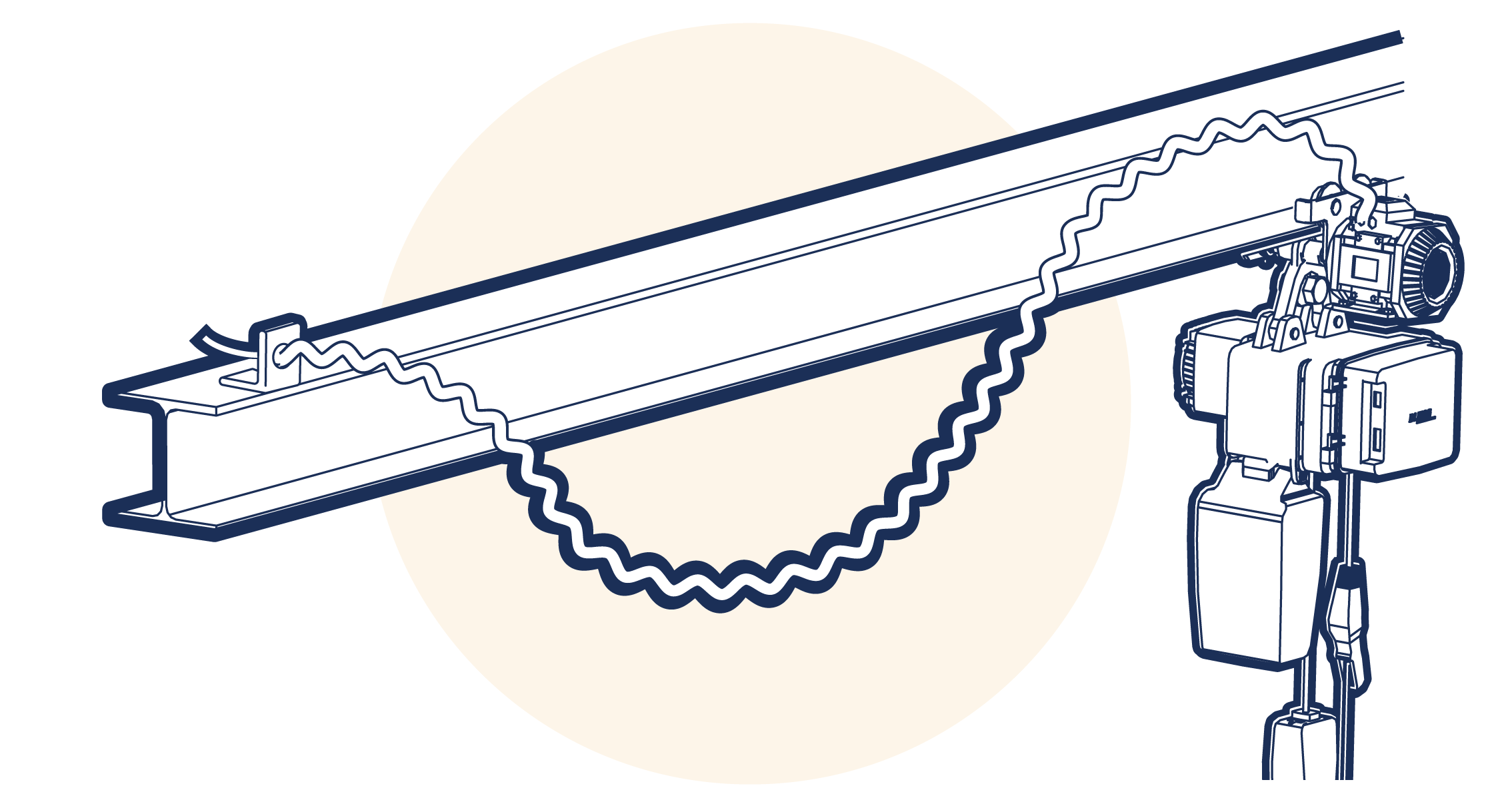
Figure 1.A6.4.6.3-1
1.A6.4.6.4 Festooned cable
With a festooned cable (Figure 1.A6.4.6.4-1 ) system, the supply cable is looped along a taut wire or ‘C’ rail running parallel to the runway track. Small sliding hangers or trolleys, from which the cable is suspended, allow it to move freely back and forth whilst maintaining the power supply. The cable may be of circular or flat-form construction, the latter being the most common. Taut wire systems are limited to lengths not exceeding 30 metres due to sag in the support wire and are only suitable for use in straight runs. They are however ideal for dirty and dust laden environments. ‘C’ rail systems are not limited in the same way. They are therefore suitable for longer runs and some types are suitable for applications which include bends. However, they are unsuitable for use in areas where a build-up of dust or other deposits can form in the rail. Both types are limited by the space required to house the bunched-up cable when the appliance is at the end of the runway track.
Festoon conductors have the advantage that the electrical connection is permanent and does not depend upon a sliding shoe which will require maintenance. However the disadvantage is that they are limited in length because space is required to accommodate the loops when bunched close. They are often used to supply the power across the bridge of electric bridge and gantry cranes and are suitable to supply power along short runway tracks.

Figure 1.A6.4.6.4-1
1.A6.4.6.5 Cable reeling drum
There are several distinct variations of this type, but they all work by storing the power supply cable on a drum and paying it out to allow movement. Some incorporate a spring to reel in the cable. When the cable reeling drum is positioned high up, the spring also provides sufficient tension to hold the cable in a shallow loop which can keep it clear of people and obstacles. This system is limited by the size of the drum and, as the cable is always under tension, it exerts a pull on the trolley which can, in extreme cases, cause the travel to be arrested or even cause the appliance to be pulled back along the runway track. However, incorporation of a swivel mounting, or a fairlead enable them to be positioned centrally and double the length served. Cable reeling drums may be used on curved runway tracks.
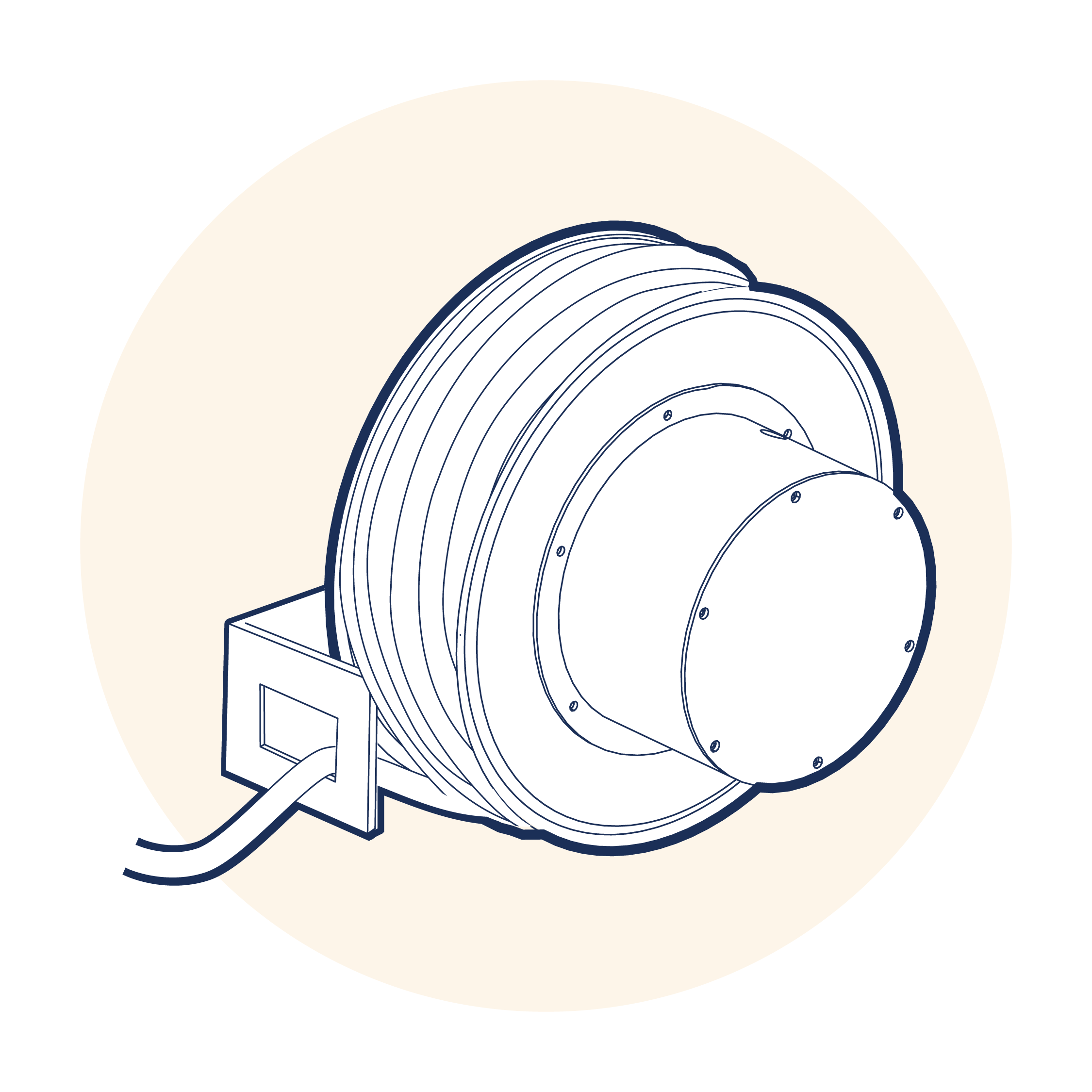
Figure 1.A6.4.6.5-1
Another variation is most commonly used to supply power to portal cranes. These are usually mounted on one of the crane legs and lay the cable into a trough on the ground as the crane moves and cable is paid out. A power drive incorporated into the drum winds the cable back when the travel direction is reversed. These reeling drums can be quite large and accommodate a considerable length of cable. Also, as the cable is not in any significant tension, they can service a long crane track.
1.A6.4.6.6 Enclosed conductors
In this system (Figure 1.A6.4.6.6-1 , Figure 1.A6.4.6.6-2 ) a linear conductor is enclosed within a protective insulating cover which has a narrow opening on the underside. A sliding shoe connects with the conductor through this opening. For a three phase power supply, four conductors are required, one for each phase and one for the earth.
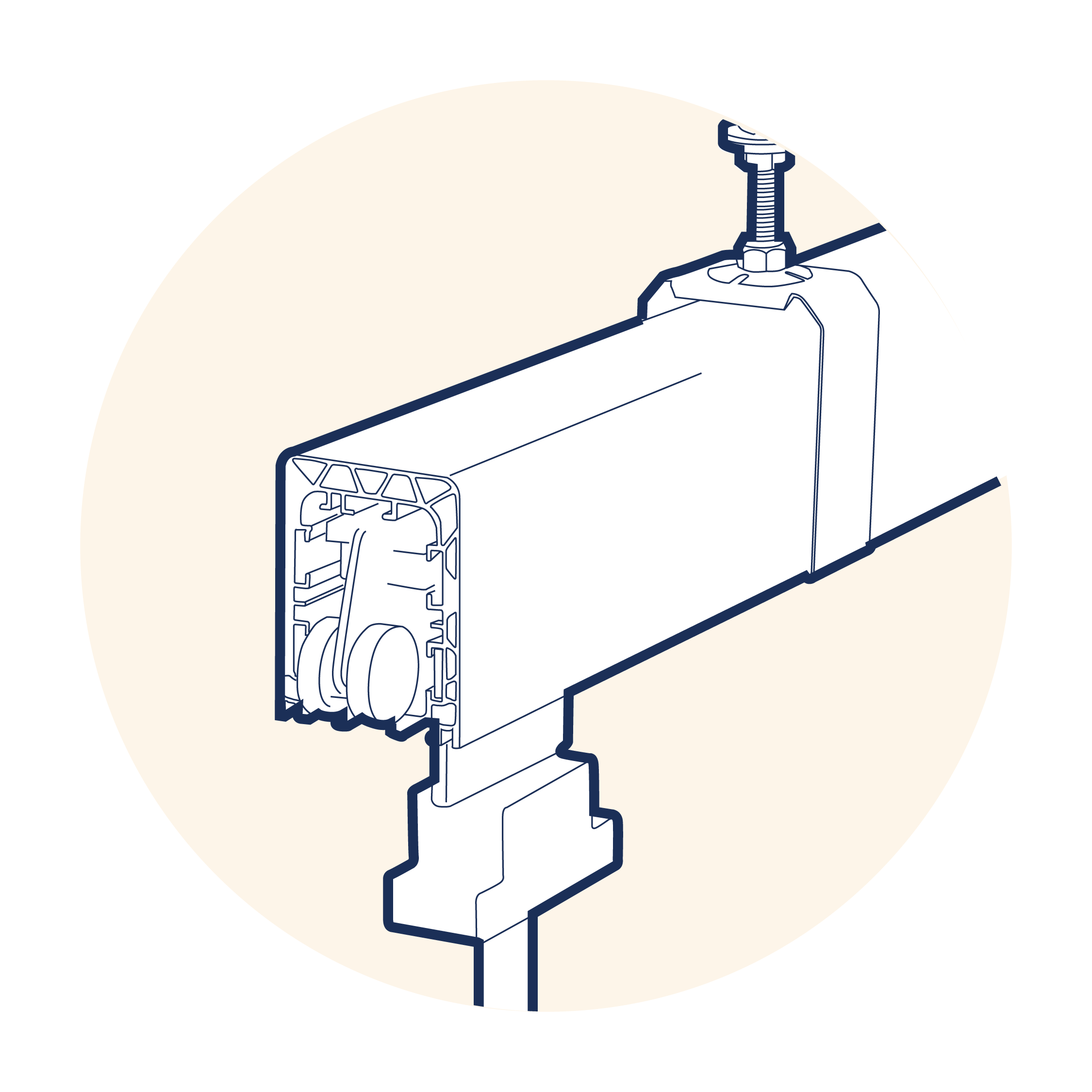
Figure 1.A6.4.6.6-1 Shrouded conductor system
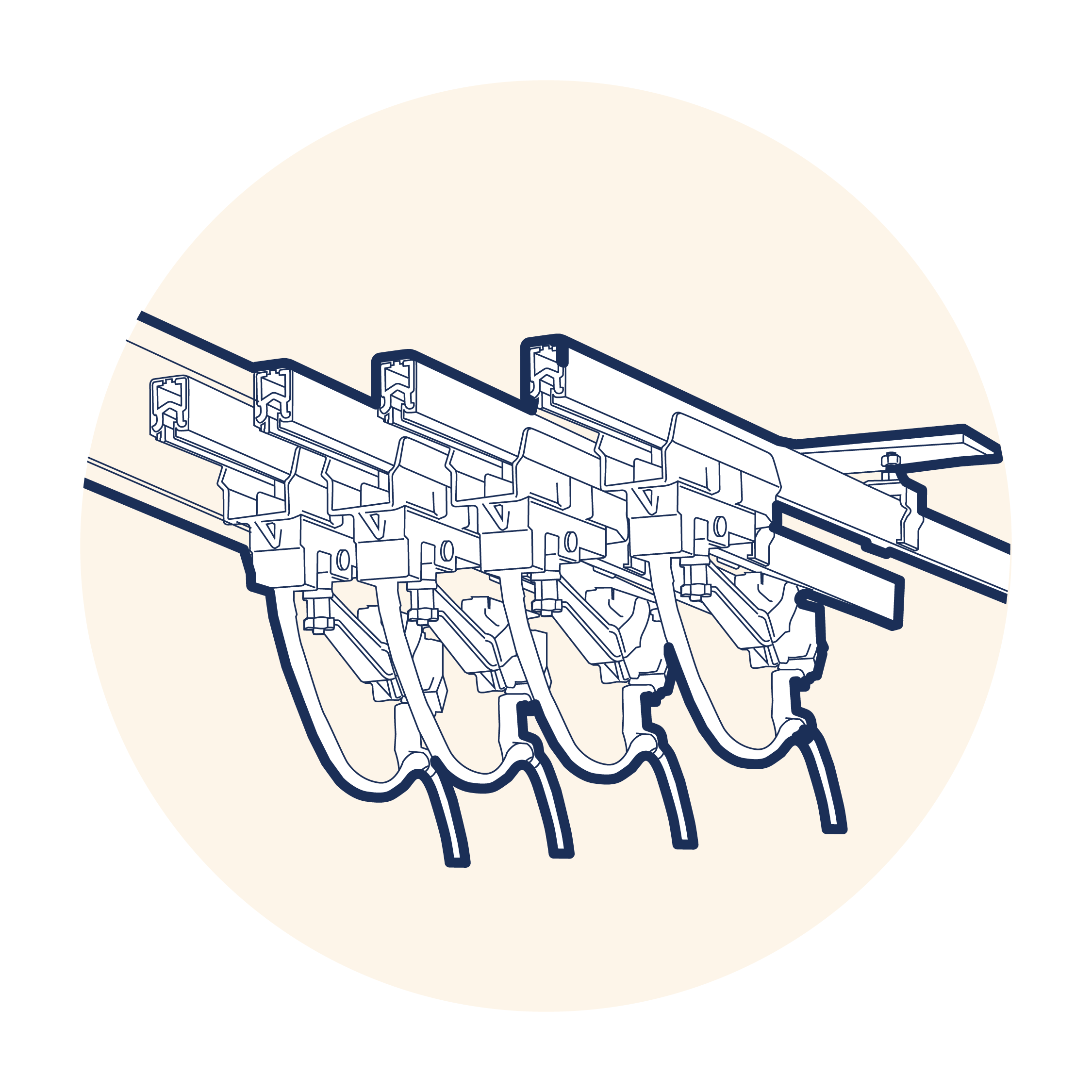
Figure 1.A6.4.6.6-2 3 phase - 4 conductor system
This system has the advantage of being able to supply power along an almost unlimited length. Because of this it is very suitable for supplying down shop power. Whilst some voltage drop will inevitably occur with long lengths, it can be countered by connecting the supply at the mid point or in extreme cases, at several points along the length.
A variation of this type is the shrouded conductor system in which the required number of conductors are enclosed within a single insulating shroud. This type has all the advantages of the individual insulated conductor and is also more compact.
These systems are unsuitable for use in certain environments, e.g. those that would require flame proofed or explosion proofed equipment. They are ideal for long travel distances and may be used on curved runway tracks.
1.A6.4.6.7 Energy Chain Cable Carrier Systems
In this system, Figure 1.A6.4.6.7-1 , the conductors are encased in an articulated chain which lays in a trough. Cross bars along the length of the carrier can be opened from the outside, so that cables can be easily inserted and plugs connected. Internal separators in the carrier separate the cables. Cables can also be held in place with an integrated strain relief. Mounting brackets fix the ends of the carrier to the machine. Besides only bending in one plane due to the rigid jointed structure, cable carriers also often only permit bending in one direction. In combination with rigid mounting of the ends of the carrier, this can entirely prevent the enclosed cables from flopping in undesired directions and becoming tangled or crushed. Cable carriers are used anywhere on cranes where moving components require power, control and communication power feeds in a flexible media. Energy Chain cable carriers are quiet in operation, lightweight and provide covered cable design that can be quickly opened. They can be used in extreme conditions such as heat-resistant or clean room environments.
It has the advantage that the electrical connection is permanent and does not depend upon a sliding shoe which will require maintenance. They are particularly suitable for feeding power across the crane bridge when the chain can be positioned alongside a bridge girder avoiding the potential hazards arising from suspended cable loops. However, there is a limit to the length which they can service.
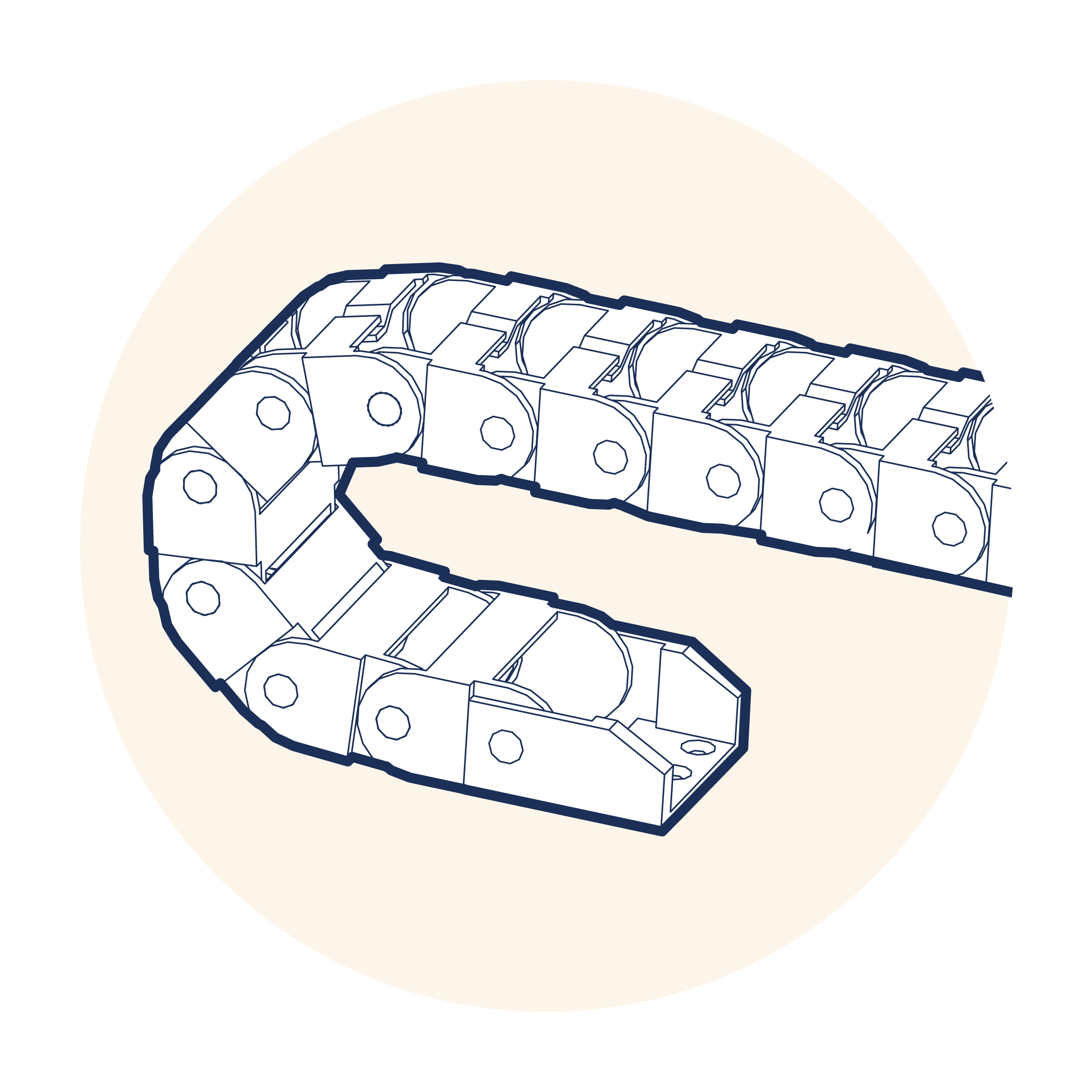
Figure 1.A6.4.6.7-1 Energy chain (shown without conductors)
1.A6.4.6.8 Trailing cables
Trailing cables, with plug and socket arrangements, may be used in certain circumstances. They enable temporary installations to be made quickly and economically. Although they may be used for short travel distances, their use should be limited as it is undesirable to have long trailing mains voltage cables. The installation must take account of the possible dangers of such a system. Any trailing cable should be suitable for the conditions of service and armoured cable should always be used. When used for temporary installations, it is important that a check is made to ensure the correct phase connection prior to operation of the appliance as the polarity of sockets is not assured.
1.A6.4.6.9 Types of control for electric power operated appliances
Modern electric power operated appliances are usually fitted with low voltage control as standard. However older hoists, special purpose hoists, winches and some cranes may not have low voltage control. Low voltage control may be 110 volt or less. Although it is quite common in many European countries to use mains voltage control, low voltage systems at 24 or 48 volt AC or DC, often referred to as Extra Low Voltage, are strongly recommended. Where fitted, this is the voltage at which all components of the lifting appliance control circuit function and is supplied by a transformer within the appliance.
Various types of controls are used with electric power operated appliances. In addition to controlling the hoist/ lower and travel motions and any speed variations, they may include other control functions such as emergency stop, a key switch for isolation of the appliance, etc. Further details for on control types can be found in the specific appliance sections of this code.
Pendant cable suspended handheld push button controls are supplied as standard with hoists. They are also commonly used with bridge and gantry cranes although larger cranes may be fitted with cabs with control panels, older types utilize drum controllers. Pendant control permits the operative to move position during operation whilst still remaining in close association with the load.
For some appliances, e.g. winches, direct online starters may be used. Wall mounted push buttons are suitable for some applications. These are often used for multi-station control applications and are useful in cases where the load has to be lifted through many floor levels or where loads have to be passed from one area to another as they allow the operative to be remote from the load. An essential requirement with this type of arrangement is the provision of emergency stop buttons to override all control positions until manually reset. They should be positioned so that they are easily accessible for the operatives or others who may need to use them. Emergency stop controls should be of a type that must be manually reset, thereby ensuring operatives are able to confirm the danger has passed or take remedial action before it is possible to operate the appliance again.
Non-conductive controls, e.g. infra-red, radio, etc. have become more commonplace in recent years. They are particularly useful in areas where direct access may not be possible as they permit the operative to be completely remote from the load and appliance. It is necessary to have the area scanned before introducing this type of control to ensure that no false signals will be sent or received as the result of interference with other equipment. As this type of control may be operated from any position, the control legends should clearly identify the direction of travel motions with symbols or clearly defined wording, e.g. east, west, etc. The appliance should be marked in a similar way. Such marking must be positioned so that it is clearly visible to the operative from any position.
1.A6.4.7 Compressed Air, its Supply Feed Systems and Controls
The production of a clean, dry supply of compressed air suitable for pneumatic power operated lifting appliances is expensive and it is less easily carried from the power source to the appliance than electricity. Due to these reasons, its use is more limited than that of electricity.
Although electric power operated lifting appliances are the usual choice for general purposes, pneumatic power operated appliances have advantages for certain applications as most of the dangers associated with electricity do not exist with compressed air.
In many cases standard pneumatic equipment can be used in atmospheres where electric equipment would require special insulation and protection to contain the danger of explosion.
when selecting pneumatic equipment for explosive environment, care should be taken to ensure that the moving components are suitable for the specific gas category and hazardous area classification.
Pneumatic motors offer variable speeds of operation. Air flow rate to the motor is controlled by the operative via a supply valve. By careful manipulation the operative can control the air delivery rate, the motor speed being governed by the volume of air supplied. At normal working pressure it is impossible to overload a pneumatic motor. Once the load increases beyond the design load of the motor, it will stall and, unlike an electric motor, it will not be harmed by this.
Although pneumatic motors are robust in design, capacity for capacity they tend to be smaller and lighter than equivalent electric motors. They will withstand a high degree of heat and moisture. Due to the internal pressure whilst in operation, the motor is self-purging. This makes standard pneumatic equipment suitable for use in steamy atmospheres, such as paper mills and laundries, and in dusty conditions, such as flour mills without any special steps being taken, unlike electrical equipment which requires enclosures to protect the equipment from their effects. If the hoist brake fails, the load will not free fall as in the case of electric equipment. The motor will act as a compressor and resist the downward movement of the load. As a result, the load will be lowered slowly by gravity.
Compressed air is less efficient than electricity. It contains a high proportion of moisture which has to be removed. Whilst motors will purge and expel this moisture when in operation, condensation will occur when the motor is idle. This will lead to corrosion and contamination of residual lubricants unless steps are taken to prevent this.
Pneumatic appliances usually exhaust spent air to atmosphere direct from the motor. The associated noise levels will be higher than with electric motors. In extreme cases, the sudden cooling of the air resulting from its expansion on release, either from the exhaust or from leaks, can cause the moisture present to freeze. This can cause a back pressure and in extreme cases blockage of the system. Although compressed air is generally considered to be less dangerous than electricity, some dangers do exist. Small leaks are usually harmless, though expensive. However, in dusty environments exhausting air and leaks can cause particles to be propelled through the air and be a hazard to eyes, etc.
Provision of a suitable air supply to travelling appliances is more difficult than with an electrical supply. High pressure flexible hoses can be considerably stiffer than electric cables. Where long travel distances are necessary, this is usually achieved by a series of supply points necessitating the disconnection and reconnection of the supply at regular intervals throughout the travel operation as pressure loss can occur in long supply systems resulting in a reduction in the effective capacity of the appliance. If hoses are subject to abrasion and wear, they can, when under pressure, suddenly burst resulting in a sudden release of compressed air. Hoses which are severed will snake and flay around when compressed air is passed through them resulting in a hazard to personnel.
1.A6.4.7.1 Air feed systems
The working capacity and operational speed of pneumatic power operated lifting appliances relies on the provision of an air supply which is at the design pressure and delivery rate. In the event of the pressure being below that for which the appliance is designed, the actual lifting capacity will be lower than that for which the appliance is rated. Equally, if the pressure is higher than intended, it may, depending on design, be possible to raise a load greater than that for which the appliance is designed, resulting in an overload situation, unless fitted with suitable overload protection. This is a danger which must be averted and this can be done by the provision of a pressure regulator in the air line near to the appliance entry port. If the air delivery rate is below that for which the appliance was designed, the operational speed will be slower than intended.
Unless steps are taken to remove it, moisture will condense in the air line and in the appliance. Although the complete removal of moisture is impracticable a suitable filter/drainer should be placed in the air line to limit this. This should be positioned at a low point in the air supply line and before any coiled or spiral hoses.
Due to the self-purging nature of air motors and the associated loss of lubricant, a regular supply of lubricant is necessary. This can be provided by an oil mist lubricator. Lubricators should be placed in the air feed as near to the appliance entry port as possible.
The air supply line should be fitted with a suitable valve to enable the appliance and its associated feed to be disconnected from the air supply. Such valves are part of the feed system which is considered to start at this point.
Although the air feed system may be plumbed directly onto the air supply line, the use of bayonet connectors has advantages. They enable appliances to be more easily removed for maintenance, relocation or storage. They also permit the ready replacement of worn or damaged hoses.
There are three main methods of feeding the air supply to pneumatic appliances:
Coiled hose.
Festooned hose.
Hose reeling drum.
1.A6.4.7.2 Coiled hose
With a coiled hose, the high-pressure hose is coiled in the manner of a tension spring giving an extension ratio of approximately 3 to 1. It is normally supplied with an extended length of 3 metres, but due to stiffness and the drag imposed on the appliance, it is best suited to shorter travel distances. In the case of push/pull units, this drag can cause the trolley to be pulled back along the runway track. By positioning the coiled hose in a central position, double the length of coverage may be achieved. Coiled hose supplies are suitable for use on curved runway tracks.
1.A6.4.7.3 Festooned hose
With a festooned hose system (Figure 1.A6.4.7.3-1 ), the high-pressure hose is formed in a loose spiral. This is supported by a taut wire which passes through the centre of the spiral and runs parallel to the runway track. The hose is then free to slide back and forth along the taut wire. Some drag is imposed on the appliance and large hanging loops of high-pressure hose can be a possible hazard. A further limit to the length of this system is the space required to house the bunched-up hose when the appliance is at the end of the runway track. Festooned hose air feed systems are suitable for use on straight runway tracks only.
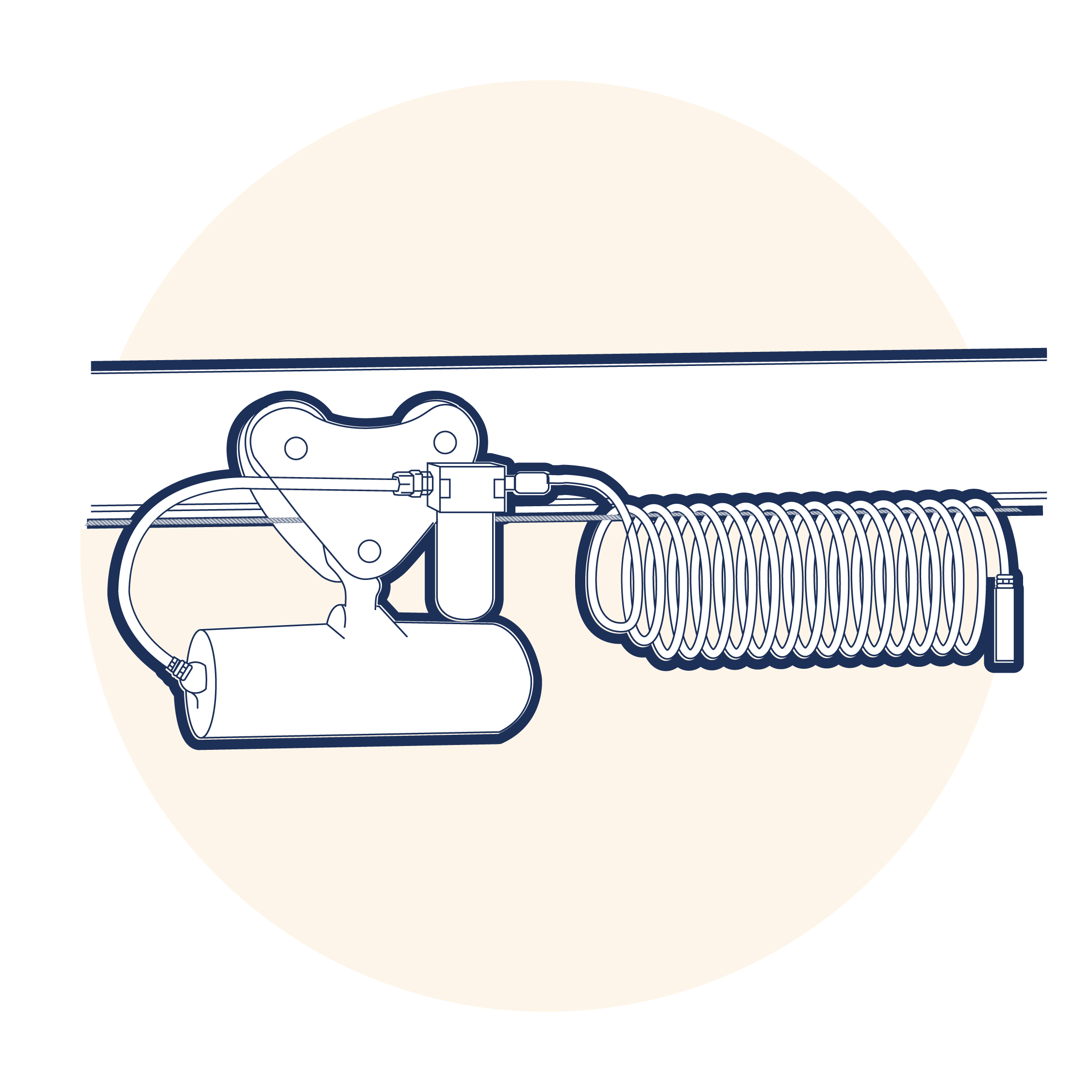
Figure 1.A6.4.7.3-1
1.A6.4.7.4 Hose reeling drum
With a hose reeling drum, the supply hose is stored on a spring-loaded drum and is paid out and recovered as the appliance travels the runway track. This system is limited by the size of the drum and, as the hose is always under tension, places a drag on the trolley which in extreme cases can cause the travel to be arrested or even cause the appliance to be pulled back along the runway track. By positioning the reeling drum in a central position, double the length of coverage may be achieved. Hose reeling drums may be used on curved runway tracks.
1.A6.4.7.5 Rigid tubing
Fixed-position, permanently installed appliances may be connected directly to the air supply line with suitable rigid tubing. However, it may be desirable to have a short flexible hose and bayonet connector feeding to the appliance to enable it to be removed for maintenance or storage.
1.A6.4.7.6 Types of control for pneumatic power operated appliances
The control of pneumatic equipment is very basic, requiring the simple opening and closing of a supply valve but this can be achieved in several ways.
The most basic method of control is the pull cord. This is the simplest option and is commonly used on pneumatic power operated hoists and trolleys. The motor control valve is fitted with a double lever arm from which the control cords are suspended. By pulling on the cord, the operative directly opens the control valve in the selected direction. An alternative to this is the twist rod control. In this case, the motor control valve stem is fitted with a twist rod. By turning the rod, the operative directly opens the control valve in the selected direction.
Pneumatic power operated winches are often fitted with lever controls. The motor control valve stem is fitted with a lever. By pulling or pushing the lever, the operative directly opens the control valve in the selected direction.
Pendant hose suspended hand held controls are available for use with hoists and winches. The hand held control houses valves which control the motions, either directly or by using air to operate the main control valve. Similar arrangements are used where remote control is necessary although these may include rigid pipe lines.
If the control is remote or utilizes a long pendant control, hose signal delay can occur resulting in over travel of the motion or a delay in commencing the operation. In some cases, electric control systems can be fitted which operate solenoid valves fitted to the appliance. These have the advantage of overcoming signal delay over long distances, but such systems may not be flame/explosion proof.
1.A6.4.8 Lifting Media
Various flexible lifting media, e.g. rope and chain, are used in association with lifting appliances. Many appliances are available with a choice of lifting media and the selection will often be a matter of personal preference. However, each has its own characteristics and will be found to be more suitable for particular applications. The individual sections of this code offer advice on the selection and safe use of the lifting media for specific appliances. Where any doubt exists, the advice of the supplier should always be sought. The following general points should however be noted.
1.A6.4.8.1 Fibre rope
The use of fibre rope is limited to low capacity manually operated winches and pulley blocks. Fibre ropes are made in a wide range of base materials, each with their own characteristics. Capacity for capacity, a larger size of rope is required than for any of the other lifting media. It is unsuitable for arduous conditions, but man-made fibres have good selective chemical resistance.
1.A6.4.8.2 Short link chain
Various grades of short link chain are used with hand and power operated hoists and with lever hoists. As a general rule, capacity for capacity, short link chain is the heaviest of the lifting media. As the links are free to articulate fully, one with another, short link chain provides the most flexible lifting medium.
Appliances which utilize short link chain incorporate a pocketed load wheel over which the chain passes, and it is this which provides the means of movement. In the case of power operated hoists, where constant speed of movement for lengthy periods of time is experienced, the action of the chain passing over the load wheel can cause long load chains to oscillate. This can lead to the load swinging and, as a result, manufacturers often impose limits on the extended dimension of their equipment.
As the chain passes over the load wheel, the slack side of the chain hangs freely in a loop. This presents a hazard which, in some cases, can be avoided by the use of a purpose made slack chain collecting box, bucket or bag. It should be noted however that such devices hang below the appliance and therefore restrict the height to which some loads may be lifted.
Chain is suitable for use in most conditions although special care must be taken when selecting the grade of chain for use in chemical and acidic environments and the supplier’s advice should always be sought in these conditions. It is particularly suited to arduous conditions as the effects of wear are less onerous than with other lifting media. To improve wear characteristics, modern chains for use in power operated hoists are case hardened.
1.A6.4.8.3 Roller chain
Roller chain is used with lever hoists and pneumatic power operated hoists. At one time, it was also used with electric power operated hoists and it is possible that an odd example of this may still be found.
Appliances which utilize roller chain incorporate a load sprocket over which the chain passes, and it is this which provides the means of movement. The pitch of roller chain is much shorter than that of short link chain and, as a result, the movement of the chain is much smoother than that of the latter. This makes it suitable for handling delicate loads and for other applications where this feature is desirable. Roller chain is the most rigid of the lifting media as it only articulates in one plane, making storage of the slack chain more difficult than with other lifting media. The slack chain is usually allowed to hang from the appliance, and it can therefore be an obstruction in certain applications. As a result, roller chain is normally used for shorter lifting applications than the other lifting media.
Roller chain is not suitable for prolonged use in dusty environments as deposits will easily build up in the small spaces between chain rollers.
1.A6.4.8.4 Wire rope
Wire rope is perhaps the most adaptable of the lifting media. It is used on power operated hoists, winches and lifting and pulling machines which use a gripping action to haul wire rope.
In the case of winches and power operated hoists, the rope is stored on a drum the capacity of which limits the available lifting height. The movement of the rope on and off the drum is very smooth and, as a result, faster speeds of operation are possible than with other lifting media. Some designs of hoist utilize a double start drum. In this case, the bottom hook follows an upward path which is central to the drum. Others utilize a single start drum where the bottom hook moves across the drum as it travels, and this can be restrictive where close end approach, or a true vertical lift is necessary.
Various constructions of wire rope are available to suit most conditions of use and the supplier’s advice should be sought as to the most suitable for the particular application.
1.A6.4.8.5 Flat woven webbing
The use of flat woven man-made webbing is occasionally used for lifting appliances. It is mostly used on lower capacity manual and power operated hoists. Although it is less resilient to arduous conditions than the other lifting media, it does have selective resistance to chemicals and is less liable to harm delicate surfaces.
1.A6.4.8.6 Safety Devices
Various safety devices are used in lifting appliances to limit the amount of movement, to protect the appliance from the worst effects of overloading or otherwise protect the appliance. These may be essential to the safe use and therefore be fitted as standard or provide additional features to the safe use of the appliance and be available as optional extras. It is therefore necessary to consult the manufacturer’s specification to establish what provisions are made as standard and discuss any additional or special requirements with the supplier.
1.A6.4.8.6.1 Motion limits
It has been a requirement that power operated wire rope hoists are provided with an upper (hoisting) limit for many years. This was required to prevent the bottom hook travelling up into the hoist body, which would result in the wire rope breaking and the load being dropped. Although prior to modern requirements it was not a mandatory requirement it is still advisable that consideration must also be given to the use of a bottom limit. If a hoist without a bottom limit is over lowered, it is possible for the rope to wind onto the drum in the reverse direction. The result will be a reversal of motion control sense and the non-operation of the upper limit. Similar limits are advisable on power operated chain hoists. In practice, it will be found that most in-service power operated wire rope and chain hoists have both upper and lower limits as standard although the method of achieving this may vary greatly. For modern hoist units it is a mandatory requirement of most modern standards to have upper and lower limits fitted that conform to the minimum essential health and safety and functional requirements.
In the now rare case of a power operated hoist found in-service and not fitted with a bottom limit, it is advisable that one is fitted. However, unless the power operated hoist is modified or taken into a new undertaking, then this advice is not mandatory and in the case of winches which are not normally fitted with motion limits, additional precautions are necessary. To prevent over-winding, steps must be taken to ensure that the bottom hook reaches the floor before the rope is fully paid out and that the rope is marked with a visual indicator, e.g. coloured marker, to warn the operative that the maximum travel has been reached. It should be noted that new safety devices are becoming increasingly more advanced and in many cases they can be retrofitted to existing lifting appliances. It is therefore recommended that users of lifting equipment continual assess older in-service equipment and fit such devices appropriate to any identified risk.
Hoisting and lowering limits are safety devices which are intended for occasional use only. In some cases, they may require manual resetting before further operation is possible. They must not be used as a means of positioning the bottom hook. In applications where this is necessary, e.g. on a production line, additional limits, known as working limits should be considered. These are of a heavy-duty type intended for regular use and are available as an optional extra.
In the case of power operated travelling appliances, the runways and tracks to which they are fitted must be provided with positive end stops to prevent the appliance running off the end of the track or colliding with the supporting structure. Again, these are ultimate safety devices and are not intended for regular use or to position the appliance. Various types of travel limits are available for applications which require the appliance to be positioned on the track or prevent the appliance travelling beyond a specified area of the track. These are available as an optional extra.
1.A6.4.8.6.2 Anti-collision and approach limiting devices
Where more than one travelling appliance is fitted to the same track, it is necessary to prevent collision or it may be necessary to prevent more than one of the appliances entering a specified area of the track. This can be achieved in several ways, the choice of which will to some extent depend on the application.
Manually operated travelling appliances, and indeed certain power operated appliances, can be fitted with extended arms and simple buffers which will limit the approach of the appliances. To prevent collision or limit the approach of power operated travelling appliances, sensor switches may be fitted to the appliances. Various types are available ranging from simple trigger switches which are mechanically operated to disconnect the power and isolate selected areas of the track, to infra-red and microwave sensors which disconnect the approach travel motions when the set distance between the units is reached. These devices permit the movement of the appliances in the reverse direction and automatically reset once the distance between the units exceeds that for which they are set.
1.A6.4.8.6.3 Overload protection
Lifting appliances can be protected from the worst effects of physical overload in several ways depending on the design of the appliance. The simplest form of overload protection used on manually operated appliances is the shear pin. This is used on lifting and pulling machines which use a gripping action on the wire rope and similar appliances to prevent excessive effort being applied to the operating lever.
Slipping clutches are sometimes used in power operated chain hoists and may also be found on some manually operated equipment. These are set to slip when the load increases beyond a predetermined amount, e.g. working load limit plus an allowance which takes into account the effects of dynamic loading. Slipping clutches are also used in some designs of lifting appliances as the upper (hoisting) limit, thereby serving a dual purpose.
To protect the electrical systems of electric power operated appliances, a wide variety of overload protection devices are used in their construction. These operate to disconnect the supply if physical or electrical overloading occurs. In some cases, it may be necessary to reset the device manually before further operation is possible whilst others automatically reset after a period of time or when the overload is removed. The primary purpose of electro-magnetic and thermo-electric devices is to prevent damage by electrical overload. They will therefore permit an excessive load to be lifted for some distance before they operate.
Load measuring or sensing devices are used to prevent physical overload by stopping the appliance operating if the load exceeds that intended. At one time these were not generally fitted as standard but since improvements to safety legislation and standards, they have become a standard feature of many appliances.
In all cases of electric power operated appliances, fuse protection must be provided in the supply system.
Although pneumatic motors stall to safety, pneumatic appliances may include a device which uses pressure springs or washers which compress under load and, if the design load is exceeded, they open a vent valve which carries the air supply to the exhaust stopping the motor from operating.
Hydraulic appliances utilize pressure relief valves which release the internal pressure in a system once this exceeds the design maximum, thereby preventing further operation until the load is reduced.
1.A6.4.8.6.4 Warning devices
Travelling or moving appliances can present a hazard to personnel. It is often sufficient to paint or mark them in distinctive colours to ensure that they are clearly visible. In some cases, greater steps are necessary. The use of warning lights and/or audio alarms should be assessed and incorporated where necessary to mitigate risk.